Method for enhancing optical parametric amplifier output magnified signal light impulse and beam quality

A technology for amplifying the signal and beam quality, applied in the laser field, it can solve the problems of poor beam quality, large aperture of OPA crystal, and can not reach the diffraction limit, etc., to achieve the effect of ensuring the signal-to-noise ratio and beam quality.

Inactive Publication Date: 2008-07-09
FUDAN UNIV
View PDF0 Cites 2 Cited by
  • Summary
  • Abstract
  • Description
  • Claims
  • Application Information

AI Technical Summary

Problems solved by technology

However, in these high-energy OPCPA systems, due to the large aperture of the OPA crystal and the use of birefringent phase matching, there is a spatial walk-off between the pump light, the signal light, and the idler light.
In addition, the pump light with megajoule pulse energy usually does not reach the diffraction limit (10-20 times the diffraction limit), and its own beam quality is relatively poor
The phase shift in the optical parametric amplification process will cause the non-ideal phase distribution of the pump light to be transferred to the signal beam, which will seriously affect the quality of the amplified signal beam
On the other hand, the study of physical experiments puts forward very high requirements on the pulse quality (signal-to-noise ratio), requiring a "clean" pulse front, but in the current high-power laser system, the problem of signal-to-noise ratio has not been well resolved good solution
But in the time domain, simply adjusting the structure of the crystal itself cannot compensate for the group velocity mismatch in the OPA crystal (R.J.Gehr, R.W.Kimmel, and A.V.Smith, Simultaneous spatial and temporal walk-off compensation frequency-doubling femtosecond pulses inβ-BaB 2 o 4 .Opt.Lett.1998, 23:1298-1300), so the phase control of the signal light pulse cannot be realized

Method used


Image

  • Method for enhancing optical parametric amplifier output magnified signal light impulse and beam quality
  • Method for enhancing optical parametric amplifier output magnified signal light impulse and beam quality
  • Method for enhancing optical parametric amplifier output magnified signal light impulse and beam quality

Examples


Embodiment example

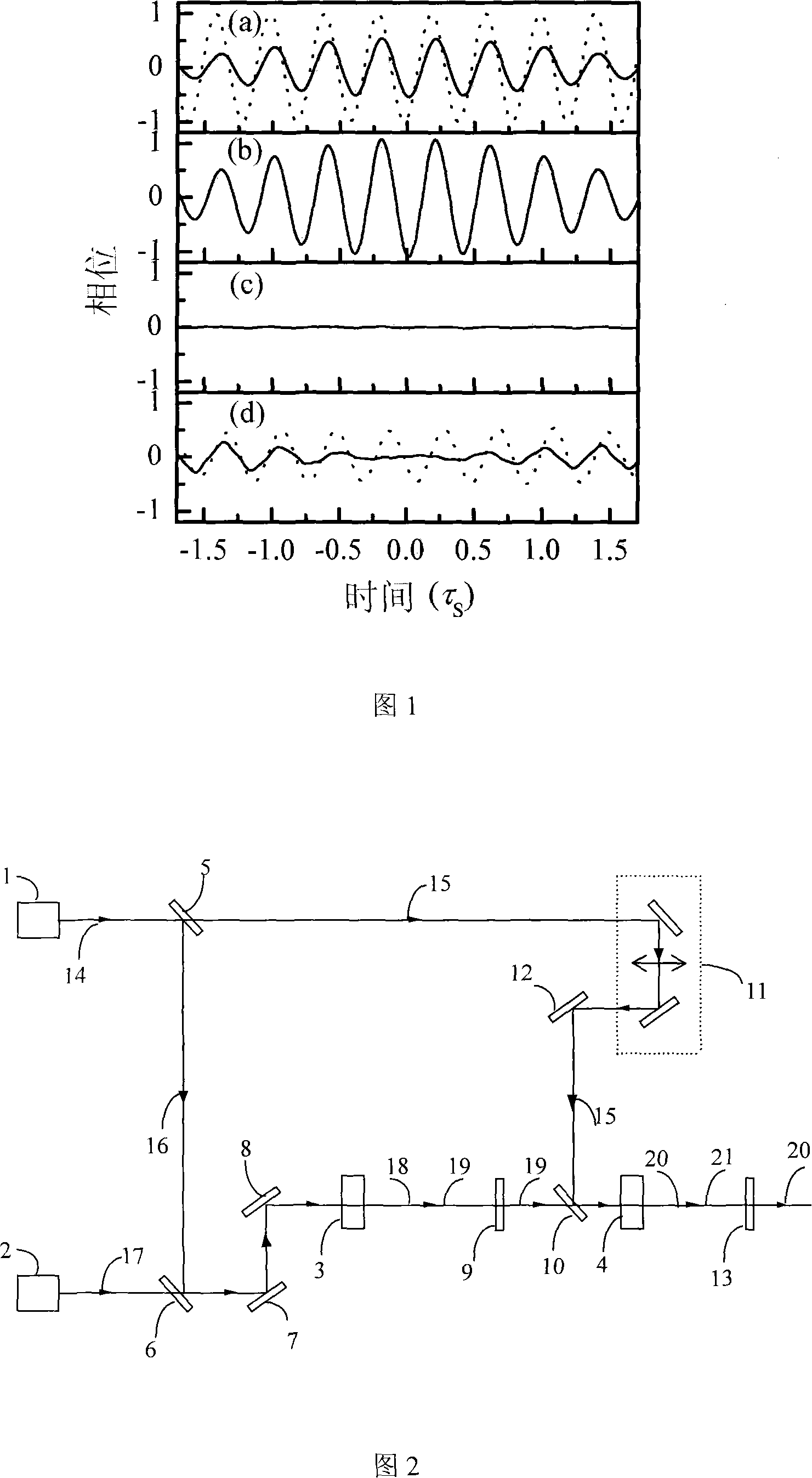
[0022] The femtosecond Ti:Sapphire laser regenerative amplifier was used as the pump source to generate a pump pulse with a pulse width of 50fs, a center wavelength of 800nm, and a repetition rate of 1-kHz. Working with diode laser pumping in TEM 00 In the mode, a continuous Nd:YVO4 laser with an average power of 0.5W and a wavelength of 1064-nm is used as the seed source. Two pieces of 10 mm long MgO: LiNbO matched with Class I 3 It is an OPA crystal. The pump light is divided into two beams (60% transmission and 40% reflection) by the beam splitter, and the two beams are respectively passed through the telescope system to obtain the same pump light intensity (90GW / cm 2 ), adjust the crystal orientation so that the wavelength of the signal light is about 1040nm to ensure that the signal light pulse and the idle light pulse have approximately the same group velocity, and adjust the light spot so that the idle light and the pump light spatially overlap.

[0023] In the spatial doma...


PUM


Abstract

The invention pertains to the technical field of laser, in particular to a method for improving the quality of light pulse and light beam of amplified signals output from an optical parametric amplifier. In the process of optical parametric amplification (OPA) or optical parametric chirped pulse amplification (OPCPA), the method utilizes an OPA device to improve the quality of the light pulse and the light beam of the amplified signals through controlling phase shifts of signal light in the pump light direction. The method avoids influences of spatial walk-off and group velocity mismatch, relaxes requirements on the quality of pump light, and improves the quality of the light pulse and the light beam of the amplified signals; thereby the method is suitable for a high-energy OPA device or a high-energy OPCPA device.

Description

Technical field [0001] The invention belongs to the field of laser technology, and specifically relates to a method for improving the quality of the output and amplified signal light pulses and beams of an optical parametric amplifier device. Background technique [0002] The high-intensity ultra-short pulse output by the high-energy laser device creates extreme physical conditions, which can be used to study new phenomena in the field of strong field physics, including: "fast ignition" inertial confinement nuclear fusion, high energy density physics, laboratory celestial bodies Physics, super acceleration of charged particles, etc. These important applications not only require laser pulses with high energy but also ensure good pulse quality. Chirped Pulse Amplification (CPA) or Optical Parametric Chirped Pulse Amplification (OPCPA) is an important means to obtain ultra-strong and ultra-short laser pulses. With a high-energy neodymium glass laser as the pump source, the OPCPA sys...

Claims


Application Information

Patent Timeline
Patent Type & Authority Applications(China)
IPC IPC(8): G02F1/35G02F1/39G02F1/355
Inventor 钱列加任红艳罗航袁鹏朱鹤元
Owner FUDAN UNIV
Why Eureka
Try Eureka