Programmed control slow-starting high stabilization great current drive device

A high-current drive, slow-start technology, which is applied in photoplate-making process exposure devices, differential amplifiers, DC-coupled DC amplifiers, etc., can solve problems such as low accuracy and large current output fluctuations, and achieve simple production and high current. Stable, simple circuit effect

Inactive Publication Date: 2008-07-23
HEFEI ADVANTOOLS SEMICON
View PDF0 Cites 16 Cited by
  • Summary
  • Abstract
  • Description
  • Claims
  • Application Information

AI Technical Summary

Problems solved by technology

However, the existing LED drive circuit needs to manually adjust the potentiometer, the current output fluctuates greatly, and the accuracy is not high

Method used


Image

  • Programmed control slow-starting high stabilization great current drive device

Examples


Embodiment Construction

[0017] The driving circuit of the present invention will be further described through embodiments below in conjunction with the accompanying drawings.

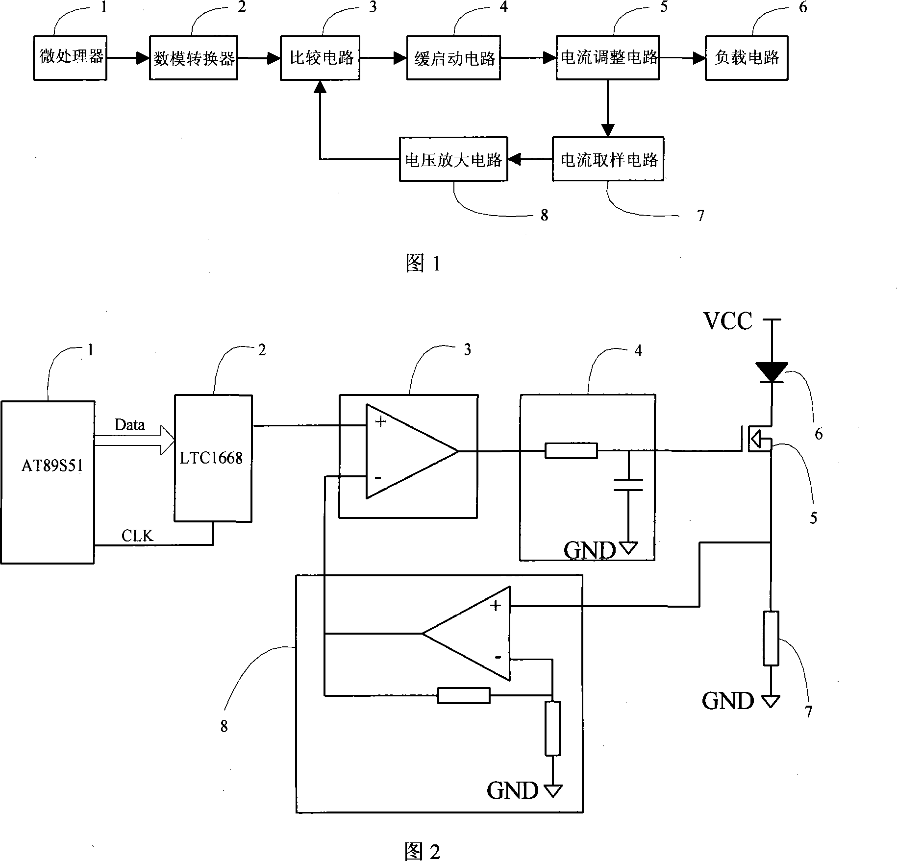
[0018] Figure 1 shows a schematic block diagram of a program-controlled slow-start high-stability high-power LED constant-current drive device. Its structure consists of a microprocessor, a digital-to-analog converter, a comparison circuit, a slow-start circuit, a current adjustment circuit, an LED load circuit, and a voltage amplification circuit. , Composed of current sampling circuit.

[0019] Fig. 2 shows a kind of actual application circuit diagram of program-controlled slow start high stable high current drive device on the high-power LED drive, its structure includes: microprocessor 1, preferably single-chip microcomputer AT89S51, but not limited to this microprocessor; Analog-to-analog converter 2, preferably LTC1668, but not limited to this digital-to-analog converter; dual-channel operational amplifier LM358, respect...


PUM


Abstract

The invention discloses a program-control delay startup high-stability large-current driver, which can control the output voltage of a high-precision digit / analogue converter via a microprocessor, control the output current of load, control a current adjustment circuit via a MOS tube to improve the output current and efficiency. The invention adds a delay startup circuit to slowly increase the load output current without abrupt change. The driver adds a high-precision sampling resistance in load to measure the current fluctuation on the load and connects the control voltage of the output current and the voltage on the sampling resistance with two inputs of a comparator via voltage amplification to form a close-loop negative feedback technique to stabilize the output current with high reliability. The invention has simple circuit, while the output drive current can reach 2A, with continuous program control and adjustable property. The invention has stable and reliable output current and low voltage impact, under the connection with different loads. The invention has wide application in constant-current control and high power LED luminous technical fields.

Description

Technical field: [0001] The present invention relates to the technical field of lithography, in particular to a direct-write lithography device for printing patterns on substrates such as wafers, printed circuit boards, mask plates, flat panel displays, biological wafers, micromechanical electronic wafers, and optical glass flat plates High power LED lighting and constant current control field. Background technique: [0002] Photolithography is used to print a pattern of features on the surface of a substrate. Such substrates may include substrates used in the fabrication of semiconductor devices, various integrated circuits, flat panel displays (eg, liquid crystal displays), circuit boards, biochips, micromechanical electronic chips, optoelectronic circuit chips, and the like. Often used substrates are semiconductor wafers or glass substrates with light-sensitive media on the surface. [0003] During lithography, a wafer is placed on a wafer stage, and a pattern of featur...

Claims


Application Information

Patent Timeline
Patent Type & Authority Applications(China)
IPC IPC(8): G03F7/20H03F3/45
Inventor 操文祥
Owner HEFEI ADVANTOOLS SEMICON
Why Eureka
Try Eureka