Cell-type car-type heating stove highly effective combustion system

A combustion system and heating furnace technology, applied in lighting and heating equipment, furnaces, furnace components, etc., can solve the problems of only about 40%, blockage of burners, long soaking time, etc., to reduce oxidation burning Loss rate, extended service life, high degree of automation effect

Inactive Publication Date: 2008-09-10
WUXI LONGSHAN TECH
View PDF0 Cites 11 Cited by
  • Summary
  • Abstract
  • Description
  • Claims
  • Application Information

AI Technical Summary

Problems solved by technology

[0003] The disadvantage of chamber type and trolley type heating furnace is that the furnace is small, and the combustion space is also small after loading the billet. Since the temperature of each point in the furnace is required to be uniform, the exhaust gas temperature is equal to or higher than the furnace temperature. These factors will lead to fuel Insufficient combustion
Generally, the exhaust gas temperature of chamber-type and trolley-type heating furnaces is as high as 1200-1300 °C, and the furnace temperature of some refractory sintering furnaces is even as high as 1600 °C. Therefore, it is difficult to configure a long-term working at such a high temperature in actual use. High-efficiency waste heat recovery device, even if a high-alloy high-efficiency heat exchanger is used, the preheating temperature can only reach about 500°C, and the highest flue gas waste heat recovery rate will not exceed 35%. The thermal efficiency of a large number of chamber furnaces with general equipment levels is 15 ~25%, even if it is a room-type or trolley-type heating furnace equipped with full-fiber furnace lining, high-alloy heat exchanger, computer control, etc., its best thermal efficiency index can only reach about 40%. It is because the exhaust gas temperature is high and the heat taken away by the flue gas is too much, which is the main reason for the high energy consumption of conventional chamber and trolley heating furnaces
[0004] The burner 1 of the conventional chamber type and trolley type heating furnace is usually arranged on the side wall of the furnace. Since the conventional burner belongs to the form of a point heat source, it cannot completely prevent the flame from directly scouring the billet when it is arranged, so the temperature difference at each point in the furnace is relatively large. The temperature difference at each point of the billet is relatively large, resulting in long soaking time and high oxidation burning rate
In order to solve the problem of high energy consumption of conventional chamber-type and trolley-type heating furnaces, some chamber-type and trolley-type heating furnaces using regenerative burners have been put into production in China at present, which have obvious energy-saving effects, but as shown in Figure 1 and Figure 1 As shown in 2, the burners arranged at the bottom are easy to be blocked by sundries, which will cause the heat supply capacity of the burners to drop quickly. The furnace temperature below the furnace is low, and the temperature difference between the upper and lower sides increases; if the arrangement is as shown in Figure 2, the blockage of the burner will cause the heat supply capacity of the entire furnace to decrease
In addition, although these furnaces adopt the regenerative combustion system, they still retain the high-temperature exhaust outlet at the end of the furnace according to the conventional furnace method. The control of the two sets of exhaust systems is relatively complicated. It will lead to large fluctuations in furnace pressure and it is difficult to adjust. Although this kind of regenerative chamber and trolley type heating furnace is more energy-efficient than conventional chamber and trolley type heating furnaces, it has the following defects in actual use:
[0007] (3) The structure of the furnace body and the layout of the pipeline are complicated, and the two sides of the furnace body occupy a large space
[0008] (4) The control of the two sets of smoke exhaust systems is complicated, and the furnace pressure fluctuates greatly
[0009] (5) The workload of old furnace transformation is heavy

Method used


Image

  • Cell-type car-type heating stove highly effective combustion system
  • Cell-type car-type heating stove highly effective combustion system
  • Cell-type car-type heating stove highly effective combustion system

Examples


Embodiment Construction

[0035] Below the present invention will be further described in conjunction with the embodiment in the accompanying drawing:

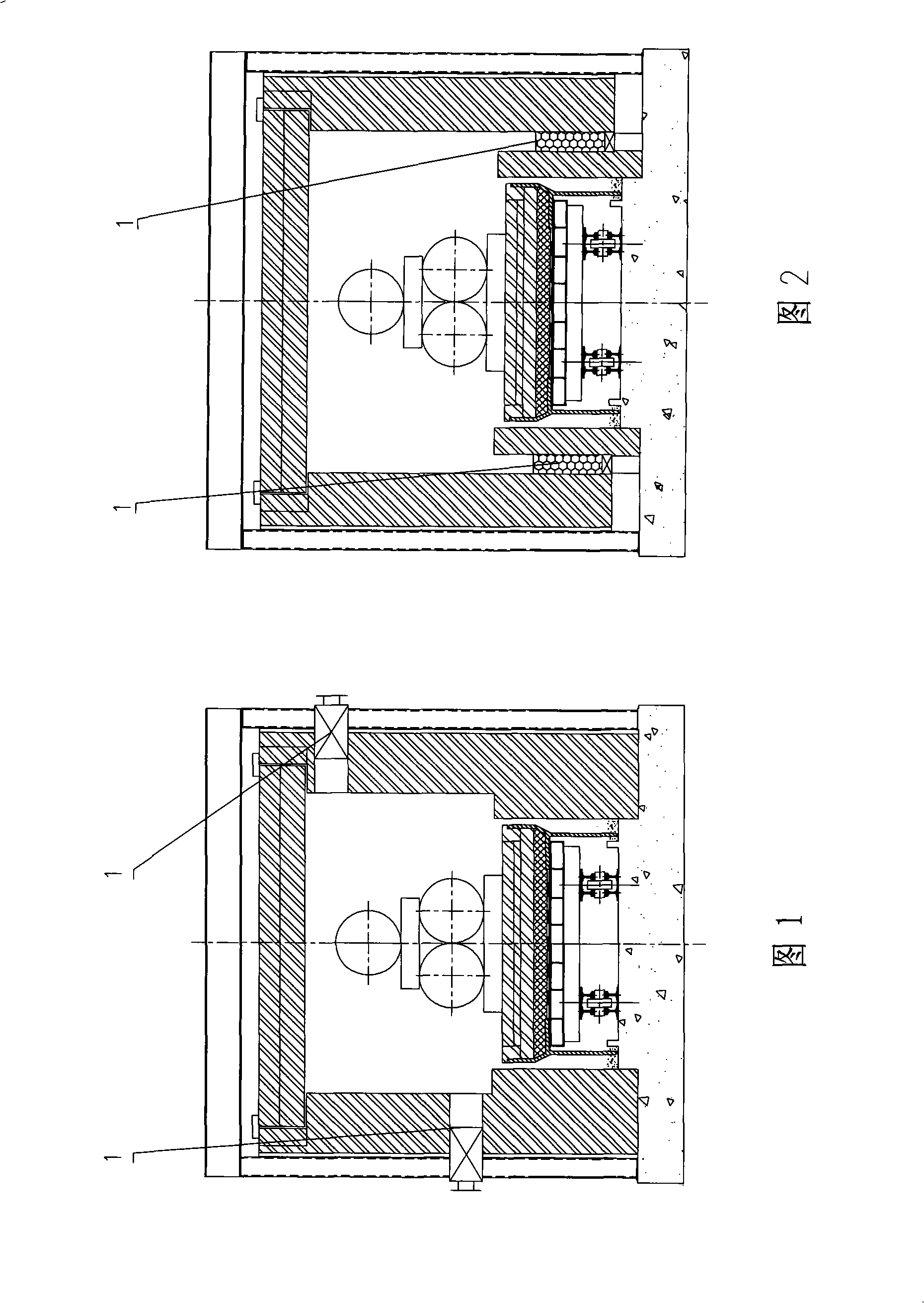
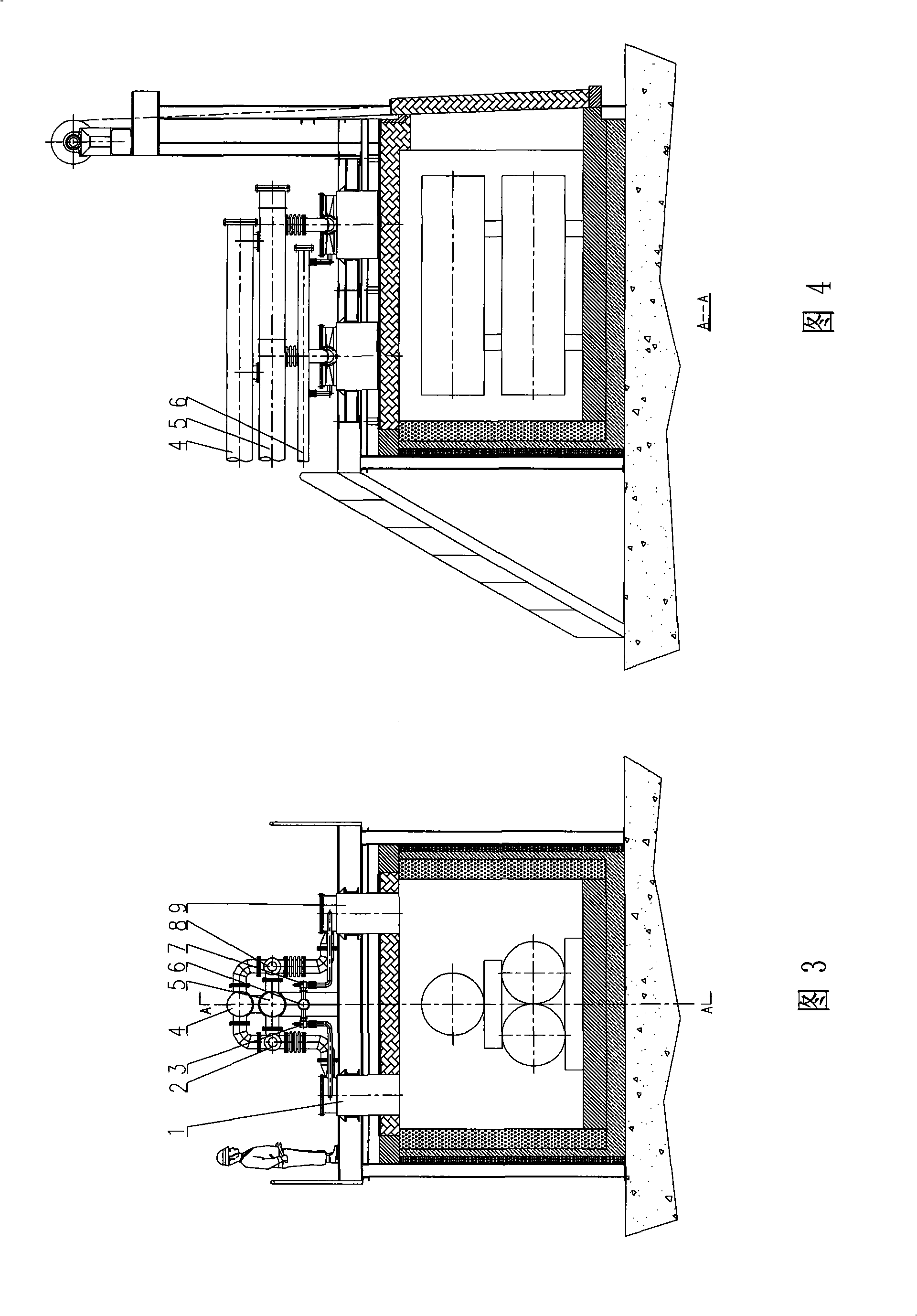
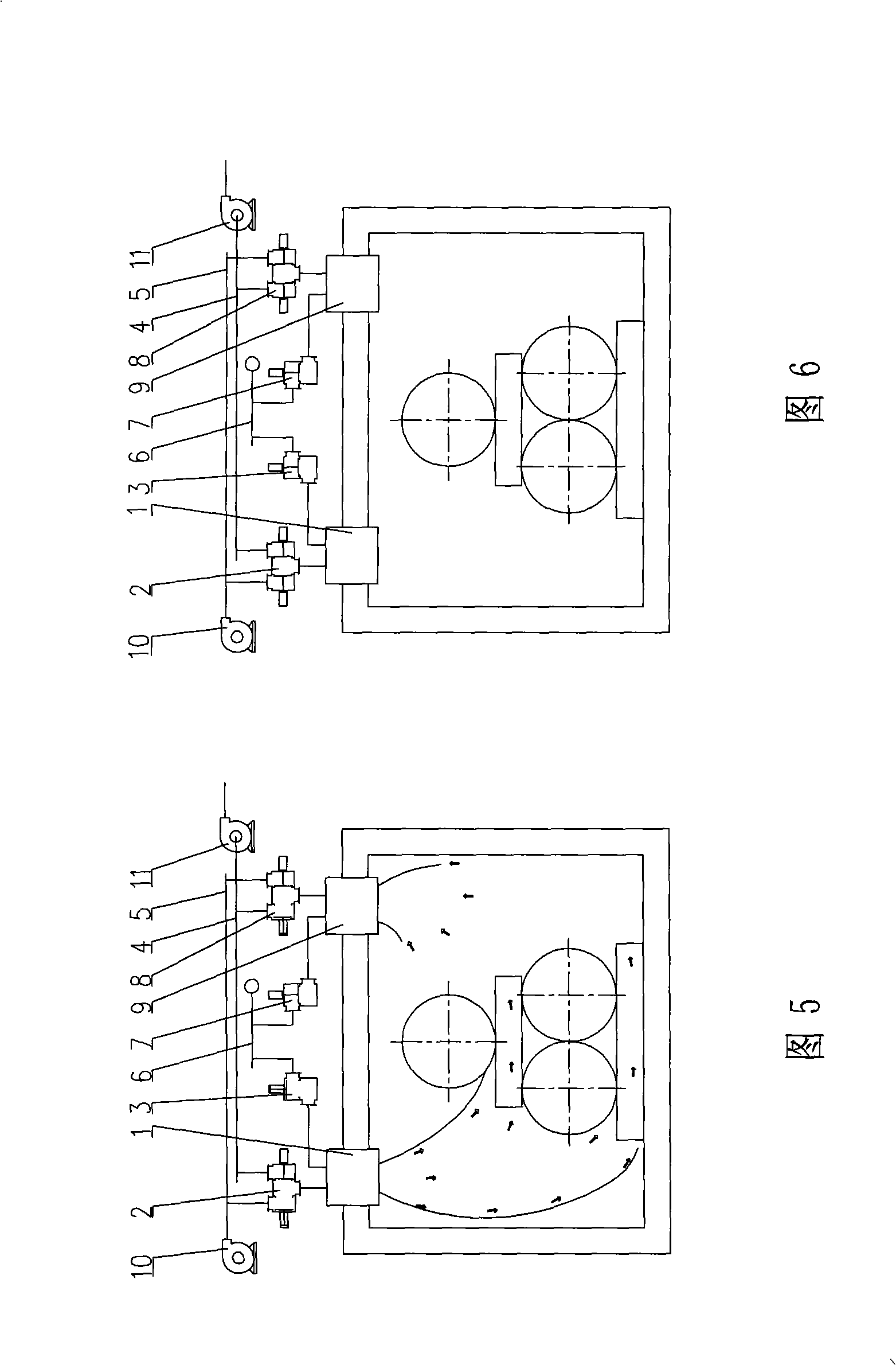
[0036] Figure 3~ Figure 7 Shown: including several pairs of regenerative left burners 1, left reversing valve 2, left gas quick cut valve 3, smoke main pipe 4, air main pipe 5, gas main pipe 6, right gas quick cut valve 7, Right reversing valve 8, regenerative right burner 9, combustion-supporting blower 10, hood 11.

[0037] Figure 3~ Figure 7 As shown, according to the charging characteristics of chamber-type and trolley-type heating furnaces, the present invention arranges several pairs of regenerative type left and right side burners on the two sides of the furnace roof that can avoid the flame scouring the billet as much as possible and obtain the largest combustion space. side. According to the requirements of different equipment levels of users, the present invention can adopt the "full decentralized" reversing control mode in which each set ...


PUM


Abstract

The invention relates to an efficient combustion system of a chamber and car bottom heating furnace, belonging to the energy-saving and environment-protecting heating furnace technique field. The invention comprises a plurality of pairs of heat accumulating left and right sides combustion nozzles which are arranged on the two sides of the furnace top of the heating furnace, wherein, the heat accumulating left side combustion nozzles are connected with a smoke pumping main and an air main through a left side reversing valve and are connected with a gas main through a left side gas quick-switch valve; the heat accumulating right side combustion nozzles are connected with the smoke pumping main and the air main through a right side reversing valve and are connected with the gas main through a right side gas quick-switch valve; the air main is connected with a combustion air fan; the smoke pumping main is connected with a smoking machine. The efficient combustion system forms the high kinetic energy U-shaped air steam inside the furnace, thereby improving the uniformity of the furnace temperature; all the flue gas generated by the combustion of half of the combustion nozzles of the whole furnace is discharged from the other half of the combustion nozzles, thereby abolishing the tail gas duct with high energy consumption and complicated structure of the prior chamber and car bottom heating furnace; the energy consumption is reduced by 40 to 60 percent and the furnace output and the blank heating quality are improved.

Description

technical field [0001] The invention relates to a high-efficiency combustion system of a chamber-type and trolley-type heating furnace, belonging to the technical field of energy-saving and environment-friendly heating furnaces. Background technique [0002] Chamber type and trolley type heating furnaces belong to the type of intermittent heating furnaces, and the operation system of one shift or two shifts is usually implemented, and the furnace structure is relatively simple. According to the thermal system, it can be divided into heating furnace and heat treatment furnace. According to the structural form, the chamber furnace can be divided into single chamber type, double chamber type, single chamber double door type and other types; trolley furnace can be divided into single furnace door and Double oven doors and other types. As far as the combustion system is concerned, these two types of furnaces are chamber-shaped furnaces, and generally the furnace is not divided i...

Claims


Application Information

Patent Timeline
Patent Type & Authority Applications(China)
IPC IPC(8): F27D23/00F27B17/00F27B9/36F27B9/30F27D99/00
Inventor 王爱中王文虎高建勋
Owner WUXI LONGSHAN TECH
Why Eureka
Try Eureka