High-temperature low-tar biomass gasifier

A gasification device and low-tar technology, applied in cracking, petroleum industry, catalytic cracking, etc., can solve problems such as the failure of subsequent unit equipment to operate normally, reduce the economic efficiency of biomass energy utilization, and increase the cost of biomass gasification. Achieve the effects of prolonging the residence time, reducing the temperature gradient in the furnace, and enhancing the gasification reaction

Inactive Publication Date: 2008-10-08
HEFEI UNIV OF TECH
View PDF2 Cites 10 Cited by
  • Summary
  • Abstract
  • Description
  • Claims
  • Application Information

AI Technical Summary

Problems solved by technology

These methods and devices generally have a common problem in practical application: the tar content in the gas is high, which leads to the failure of normal operation of subsequent unit equipment due to tar blockage
This method can indeed reduce the tar content in the gasification mixed gas and increase the calorific value of the gas, but it uses an external heat source or the heat produced by the combustion of the gas itself, sacrificing the external energy and increasing the investment in complex equipment. On the other hand, the economic efficiency of biomass energy utilization is reduced; some scholars simply develop and use a set of methods and devices specially used for pyrolysis of tar in biomass gas outside of biomass gasifier, such as the one disclosed in Chinese patent CN101117589A A biomass gas tar cracking method and device, another example is the biomass gas tar pyrolysis method and device disclosed in Chinese patent CN101130698A, etc.
The use of these methods and devices will directly increase the cost of biomass gasification, and make the gasification process complex and cumbersome to operate

Method used


Image

  • High-temperature low-tar biomass gasifier
  • High-temperature low-tar biomass gasifier
  • High-temperature low-tar biomass gasifier

Examples


Embodiment Construction

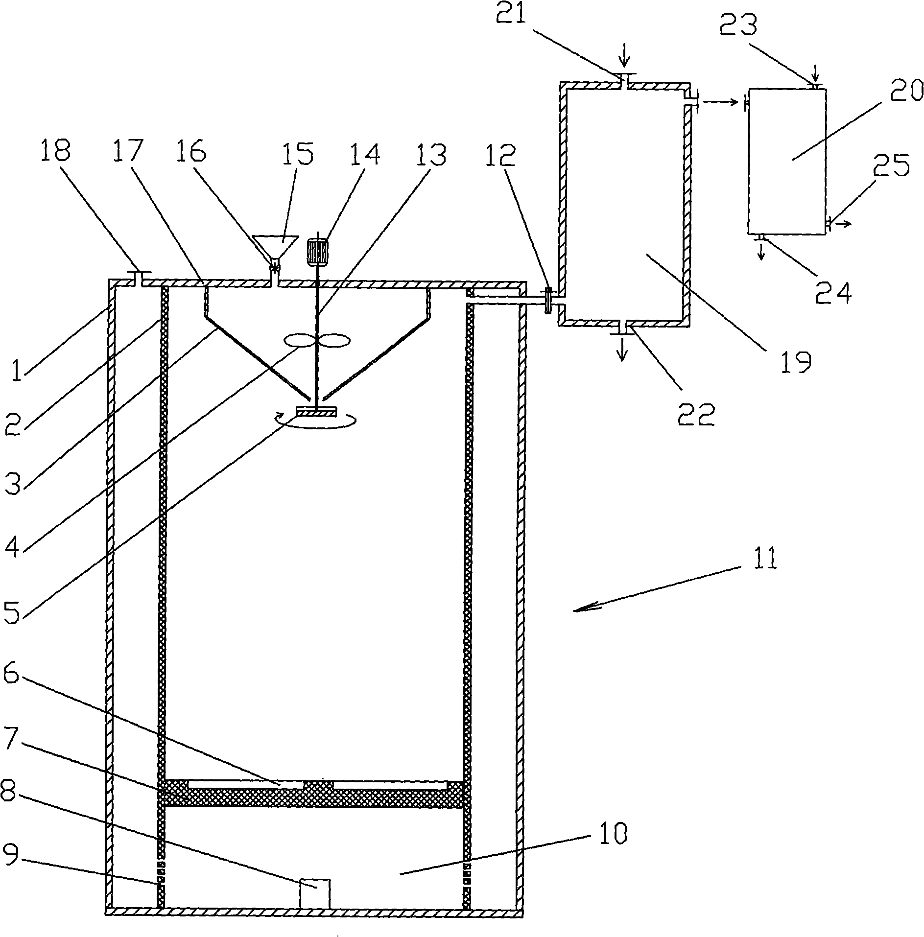
[0026] see figure 1 , feeder 15, gasifier 11, tar catalytic cracking reaction cylinder 19 and heat exchanger 20 are sequentially connected, wherein, the connecting pipe 12 connecting gasification furnace 11 and tar catalytic cracking reaction cylinder 19 is connected with the interior of gasification furnace 11 Tube 2 upper ends communicate.

[0027] The feeder 15 is fixed on the furnace roof 17, and a star-shaped sealing rotary valve 16 is arranged on the pipeline at the lower end of the feeder, and the outlet of the star-shaped sealing rotary valve 16 communicates with the preheating hopper 3 .

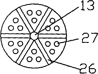
[0028] The gasification furnace 11 is set as a sleeve structure by the inner cylinder 2 and the outer cylinder 1, and an annular cavity is formed therebetween; in the inner cylinder 2, a preheating furnace connected to the feeder 15 and connected to the feeder 15 is installed. The hopper 3 is provided with a rotatable distribution grid 5 below the outlet of the preheating material ...


PUM


Abstract

Disclosed is a high temperature low tar biomass gasification device which is characterized in that the gasification device is composed of the sequential connection of a feeding unit, a gasifier, a tar catalytic cracking reaction cylinder and a heat exchanger; the gasifier is designed to the sleeve structure through an inner cylinder and an outer cylinder; an annular hollow cavity is formed between the inner cylinder and the outer cylinder; a preheating hopper which is hoisted on the lower end surface on top of the gasifier and communicated with the feeding unit is arranged in the inner cylinder; the bottom part of the inner cylinder is a slag storage chamber; the annular hollow cavity is used as the preheating cavity of the gasification agent; the inlet of the gasification agent is communicated with the annular hollow cavity; the outlet of the annular hollow cavity is the vent hole arranged on the lateral wall of the slag storage chamber; the combustion gas generated in the inner cylinder leads to the tar catalytic cracking reaction cylinder through the combustion gas outlet; the heat exchange medium is the generated combustion gas in the tar catalytic cracking reaction cylinder and the cold gasification agent; the gasification agent outlet of the heat exchanger is communicated with the gasification agent inlet of the gasifier. The high temperature low tar biomass gasification device has the advantages of avoiding the external heat source, simple and compact structure, improving the heat value of the combustion gas, improving the gasification efficiency and lowering the tar content obviously.

Description

technical field [0001] The invention relates to a gasification device, in particular to a high-temperature and low-tar biomass gasification device. Background technique [0002] Biomass gasification is an important way to utilize biomass energy. It is to make biomass undergo a partial combustion reaction in a gasification device in an oxygen-deficient state to produce a mixed gas containing methane, carbon monoxide and hydrogen. At present, the biomass gasification methods and devices developed and applied on a large scale mainly include updraft fixed bed, downdraft fixed bed, fluidized bed, etc. These methods and devices generally have a common problem in practical application: the high tar content in the gas causes subsequent unit equipment to fail to operate normally due to tar blockage. In response to this problem, many scholars have proposed some solutions, which can be summed up by increasing the gasification reaction temperature, speeding up the reaction rate, and in...

Claims


Application Information

Patent Timeline
Patent Type & Authority Applications(China)
IPC IPC(8): C10B53/02C10G11/00
Inventor 唐志国程建萍
Owner HEFEI UNIV OF TECH
Why Eureka
Try Eureka