
Nano-carbon generating apparatus

A generation device and nano-carbon technology, applied in nano-carbon, nano-technology, nano-technology and other directions, can solve the problems of burning danger, difficulty in continuously taking out the carbon generated by catalyst input, and difficulty in maintaining a reducing atmosphere, etc.

Inactive Publication Date: 2008-10-29
KK TOSHIBA
View PDF1 Cites 1 Cited by
  • Summary
  • Abstract
  • Description
  • Claims
  • Application Information

AI Technical Summary

Problems solved by technology

[0004] However, in the conventional treatment technology of organic treated substances, in order to carry out batch treatment in a high-temperature furnace, after putting in a catalyst and reacting, the furnace is cooled to take out the carbon, which is very time-consuming.
In addition, if carbon is taken out while maintaining a high temperature, there is a danger of burning
Furthermore, there is also the following problem: since the reaction occurs in a reducing atmosphere, it is difficult to maintain a reducing atmosphere when the project is enlarged, and it is also difficult to input the catalyst and continuously take out the generated carbon.

Method used


Image

  • Nano-carbon generating apparatus
  • Nano-carbon generating apparatus
  • Nano-carbon generating apparatus

Examples


no. 1 Embodiment approach

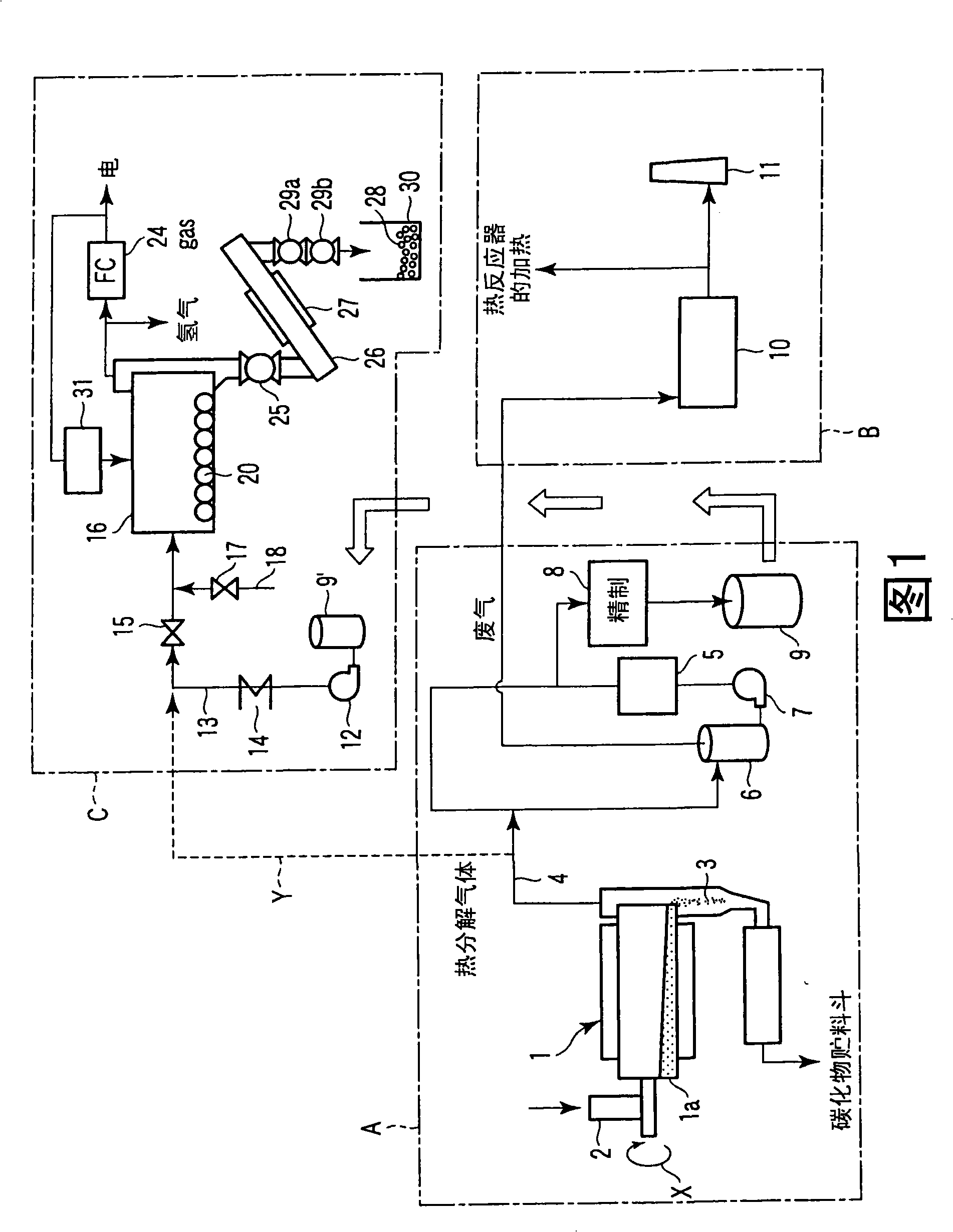
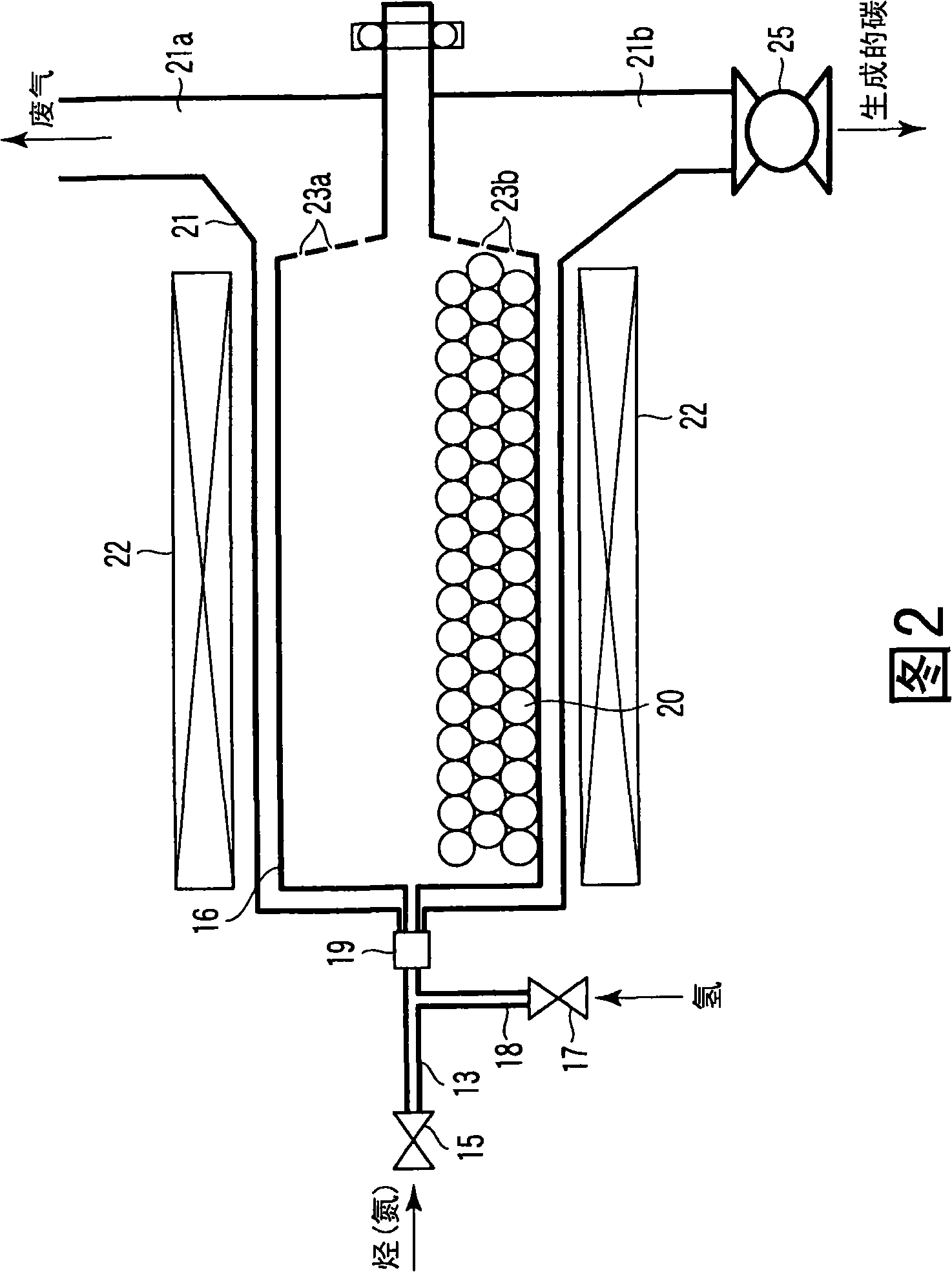
[0025] Refer to Figure 1 and Figure 2. Here, FIG. 1 is a process flow diagram of a nanocarbon production apparatus according to a first embodiment of the present invention. FIG. 2 is an enlarged explanatory diagram of a rotary kiln, which is a configuration of the nanocarbon production apparatus of FIG. 1 , and its surroundings. The process flow chart includes: from raw material input into thermal decomposition device to recovery and refining of liquefied matter to obtain biomass, block A, to block B of waste gas combustion and exhaust obtained in block A, from bio-oil Refined box C that is heated to vaporize to nanocarbons.

[0026] Reference numeral 1 in the figure represents a thermal decomposition mechanism that rapidly thermally decomposes a raw material and a catalyst at a temperature of about 500° C., which are woody biomass resources that are organically processed, and are broken into pieces. This thermal decomposition mechanism 1 has a drum 1a rotating as indicated ...

no. 2 Embodiment approach

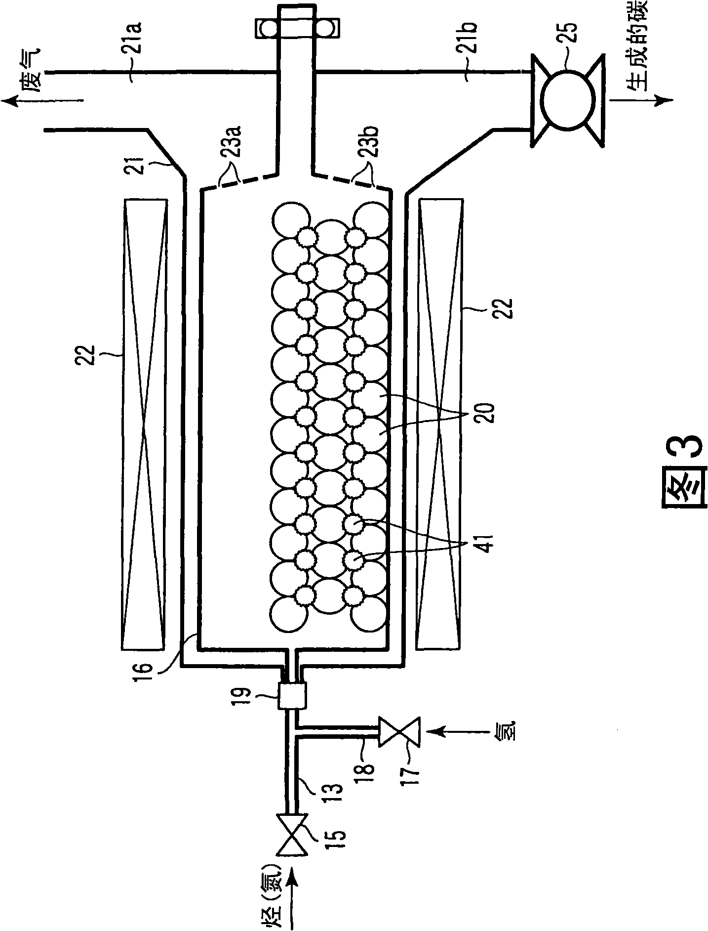
[0044] Refer to Figure 3. Fig. 3 shows only the rotary kiln and its surroundings of the nanocarbon production apparatus of the second embodiment. Here, the same components as those in Fig. 1 and Fig. 2 are given the same symbols and their explanations are omitted.

[0045] The present embodiment is characterized in that, in addition to the SUB metal balls 20 , a large number of superhard balls 41 made of hard ceramics are accommodated in the rotary furnace 16 so as to be mixed with these metal balls 20 .

[0046] According to the second embodiment, the surface of the metal ball 20 is activated by cutting the surface of the metal ball 20 with the superhard ball 41 constantly, and the carbon generated on the metal ball 20 can be peeled off. In addition, since the inner wall surface of the rotary kiln 16 can also be scraped off by the superhard ball 41, it is necessary to harden the inner wall surface of the rotary kiln 16.

[0047] In addition, not only putting the superhard b...

no. 3 Embodiment approach

[0049] This embodiment, not shown in the figure, is characterized in that the above-mentioned metal balls and superhard balls with a rough surface are arranged in the rotary furnace, and the metal balls are hollow and have a volume density equal to that of the superhard balls.

[0050] According to the third embodiment, the volume densities of the metal balls and the superhard balls are equal, so that the metal balls and the superhard balls in the rotary kiln can be uniformly mixed.


PUM


Abstract

A nanocarbon generation equipment designed such that organic processed materials can be quickly thermally decomposed therein and the decomposed materials are then quenched and liquefied to obtain liquefied materials is disclosed. This equipment comprises thermal reactor for quickly thermally decomposing the organic processed materials, apparatus for recovering the liquefied materials which are liquefied through quenching of thermally decomposed organic processed materials, a rotary furnace to be filled with a reducing atmosphere and loaded with hydrocarbons to be obtained through vaporization of liquefied materials after impurities contained in the liquefied materials are removed, and metal balls made of a metal selected from stainless steel, iron, nickel, chromium and an optional combination thereof,; wherein the hydrocarbon introduced into the rotary furnace is decomposed into carbon and hydrogen, thus enabling nanocarbon to be produced through vapor-phase growth.

Description

technical field [0001] The present invention relates to a nano-carbon production device for rapid cooling and liquefaction of thermally decomposable organic processed materials such as biomass and waste. Background technique [0002] In recent years, from the perspective of environmental issues, energy issues, or material resource issues, technologies have been developed for the following situations: appropriate treatment of various wastes such as industrial wastes, and extraction of energy and energy without discharging environmental pollutants. material is used effectively. Conventionally, as a waste disposal technique, the technique described in Unexamined-Japanese-Patent No. 11-61158 (patent document 1), for example is known. [0003] Patent Document 1 discloses a technique as follows: plastic is melted inside a pyrolysis tank, the plastic in a molten state is brought into liquid phase contact with a primary catalyst layer made of activated carbon to undergo thermal dec...

Claims


Application Information

Patent Timeline
Patent Type & Authority Applications(China)
IPC IPC(8): C01B31/02B82B3/00
CPCC01B31/0206B82Y30/00B82Y40/00C01B32/15B82B3/00B82Y99/00
Inventor 野间毅伊部英纪杉山英一今井正小城和高今井洁
Owner KK TOSHIBA
Learn More