Viscous microstructure preparation method

A manufacturing method and microstructure technology, applied in microstructure technology, microstructure devices, chemical instruments and methods, etc., can solve problems such as failure to meet mass production requirements, changes in fiber structure characteristics, and inability to reuse

Inactive Publication Date: 2008-11-26
CONTREL TECH CO LTD
View PDF0 Cites 4 Cited by
  • Summary
  • Abstract
  • Description
  • Claims
  • Application Information

AI Technical Summary

Problems solved by technology

But the disadvantage of this method is that not only expensive equipment such as electron beam lithography system, metal sputtering and plasma etching equipment are needed
In addition, its production rate is also very slow, and it cannot be produced in a large area, so it cannot meet the needs of mass production
At the same time, the fiber structure is manufactured by etching, so the characteristics of the fiber structure are also changed, making it impossible to reuse
[0005] As for Sitti, millions of artificially synthesized Silicone rubber fibers are prepared by the molding method. Experimental results show that this fiber can carry an object with a mass of 0.3 grams per square centimeter. Therefore, the disadvantage of this method is, Although the molding method can be quickly mass-produced, the mold cannot be reused, so it does not meet the needs of mass production
[0006] Dhinojwala and Zhao used synthetic carbon nanotubes as the spatulate structure on gecko toes. Although the adhesion force equivalent to the spatulate structure can be obtained, the disadvantage of this method is that the growth temperature of carbon nanotubes is too high, and Cannot grow directly on soft polymer substrates

Method used


Image

  • Viscous microstructure preparation method
  • Viscous microstructure preparation method
  • Viscous microstructure preparation method

Examples


Embodiment Construction

[0034] In order to describe in detail the technical characteristics of the present invention, the following two preferred embodiments are given and are described as follows in conjunction with the accompanying drawings, wherein:

[0035] Such as Figure 1 to Figure 5 As shown, the manufacturing method of a viscous microstructure provided by the first preferred embodiment of the present invention mainly has the following steps:

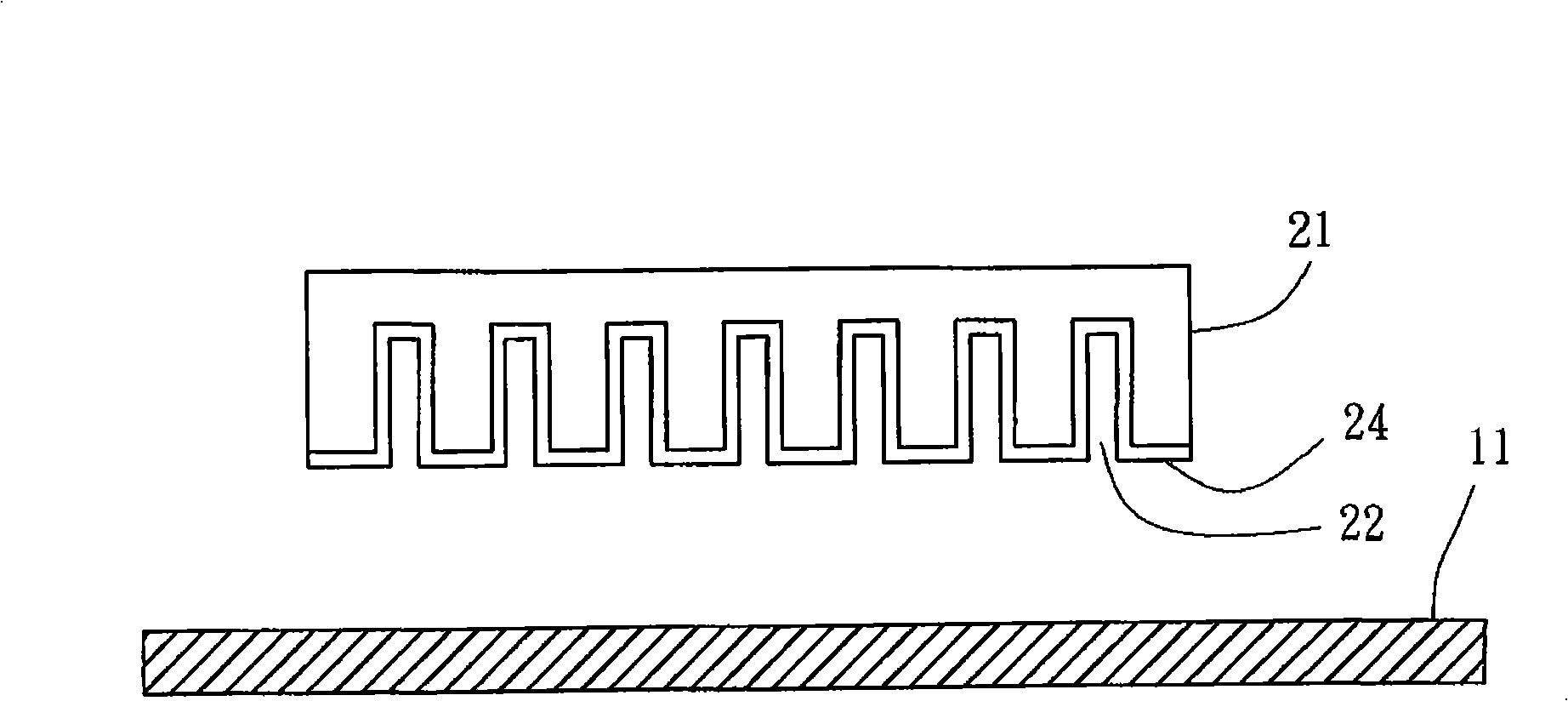
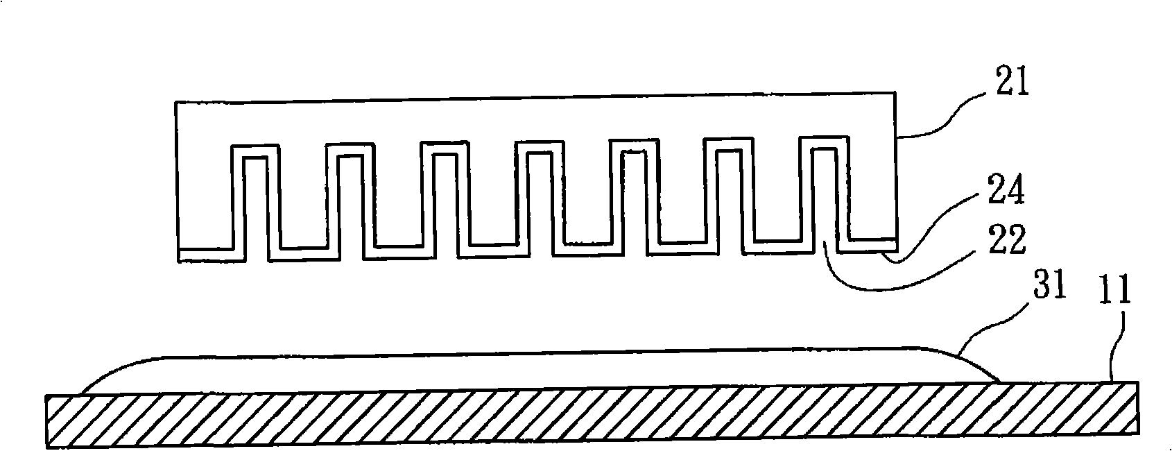
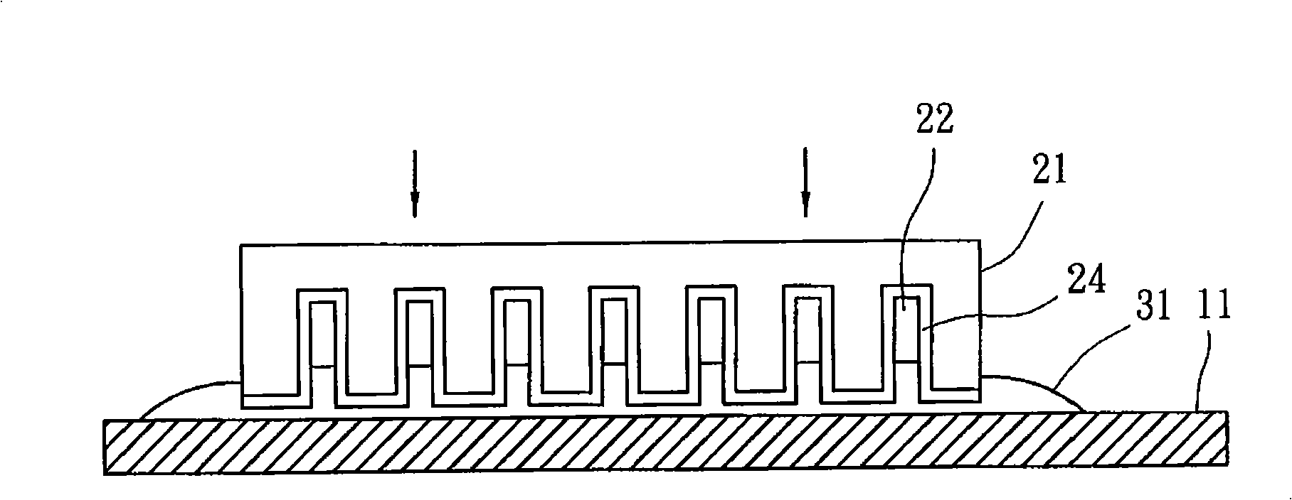
[0036] a) Prepare a substrate 11 and a mold 21: as figure 1 As shown, the bottom surface of the mold 21 has a plurality of nano-scale grooves 22, each of which has a predetermined depth, and the diameter of each of the grooves 22 is between 0.01 and 5 microns. The bottom surface of the mold 21 is provided with a layer of release agent 24 , and the release agent 24 covers the bottom surface of the mold 21 and the groove walls of the grooves 22 . The mold release agent 24 helps to pull out the mold, allowing the finished product to break away from the ...


PUM

PropertyMeasurementUnit
diameteraaaaaaaaaa
heightaaaaaaaaaa

Abstract

A method for manufacturing viscosity microstructure comprises the procedures as follows: a) a base plate and a mould are prepared and the bottom of the mould is provided with a plurality of nano-scale sockets; b) a liquid impression layer is arranged on the base plate; c) the mould is pressed under the base plate, so the liquid impression layer goes into the socket to a preset depth, thus forming a substrate and a nano-bulge arranged on the substrate; and air in the socket is compressed; d) the impression layer is turned into solid state by solidification; and e) demoulding, the mould is pulled upwardly off the base plate. Due to the bounce produced by the compressed air in the socket, the nano-bulges formed in the socket can be withdrawn from the sockets easily. The substrate and the nano-bulges are combined together to form the viscosity microstructure. Therefore, the requirements of mass production and low cost can be met.

Description

technical field [0001] The invention relates to the manufacturing technology of nanostructures, in particular to a method for manufacturing viscous microstructures. Background technique [0002] Press, the existing known nano-stickers are mainly based on the technology known from the toe skin of geckos in nature, and mainly use the extremely high-density spatulate structure on the toe to generate van der Waals force on its adsorption surface to achieve adsorption. Effect. The existing nano-sticker achieves the adsorption effect by the high-density cilia on its surface. [0003] Among the currently known manufacturing techniques of nano-stickers, there are AndreK.Geim (A.K.Geim et al., Nat.Mater.2, 461 (2003)) of the University of Manchester in the United Kingdom, Metin sitti of the University of Carnegie Mellom in the United States (M.sitti et al ., J.Adhesion Sci.Technol., 18, p 1055(2003)), Ali Dhinojwala of Akron University (B Yurdumakan et al., Chem.Commun., p3799(2005...

Claims


Application Information

Patent Timeline
Patent Type & Authority Applications(China)
IPC IPC(8): G03F7/00B81C5/00B81C99/00
Inventor 蔡友谅谢博彬
Owner CONTREL TECH CO LTD
Why Eureka
Try Eureka