Process for removing organic sulfur in low-temperature condition

A technology of low temperature conditions and process methods, which is applied in separation methods, chemical instruments and methods, and dispersed particle separation, etc., can solve the problems of inability to recover sulfur element and inability to regenerate solid catalysts, and achieve low operating costs, simple operation, and low investment. Effect

Inactive Publication Date: 2008-12-10
KUNMING UNIV OF SCI & TECH
View PDF7 Cites 12 Cited by
  • Summary
  • Abstract
  • Description
  • Claims
  • Application Information

AI Technical Summary

Problems solved by technology

[0012] Most of the organic sulfur removal processes mentioned in the above patents are only suitable for low-concentration organic sulfur, and t

Method used


Image

  • Process for removing organic sulfur in low-temperature condition
  • Process for removing organic sulfur in low-temperature condition
  • Process for removing organic sulfur in low-temperature condition

Examples


Embodiment 1

[0030] 1. Preparation of absorption liquid:

[0031] 1. Organic sulfur absorption solution and its preparation: 5ml of hexahydropyridine (chemically pure), 50ml of ethanol (chemically pure), 1ml of KOH with a concentration of 1mol / L and distilled water were prepared into 100ml of organic sulfur absorption solution for use.

[0032] 2. Regenerated gas H 2 Preparation of S absorption solution: weigh 1.62 grams of FeCl 3 and 0.72 g of 50% Mn(NO 3 ) 2 solution (element molar ratio Mn:Fe=0.2), dissolved together in 200mL deionized water, fully stirred and dissolved to make Fe 3+ Concentration is the composite ion absorption liquid of 0.05mol / L; Add 2.92 grams of EDTA and 2.18 grams of sulfosalicylic acid as stabilizer (metal ion Fe 3+ and the total molar ratio of the stabilizer is 1:2); with NaCO 3 and NaHCO 3 Control the pH of the solution to 9, and set it aside.

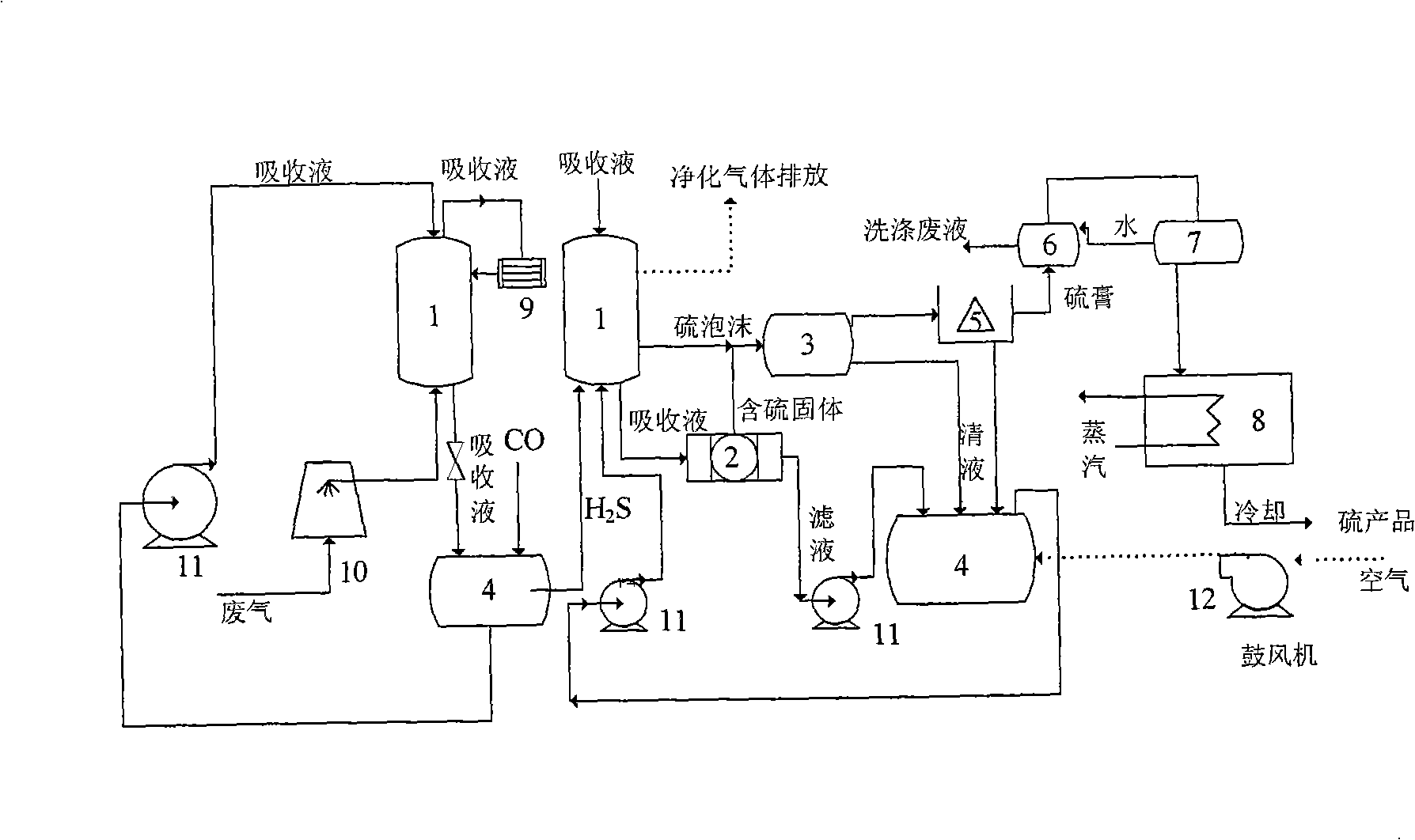
[0033] 2. The process steps of low temperature organic sulfur removal are:

[0034] 1. After cooling the sulf...

Embodiment 2

[0039] 1. Preparation of absorption liquid:

[0040] 1. Organic sulfur absorption solution: mix 10ml of hexahydropyridine, 50ml of ethanol, and 1ml of Na with a concentration of 1mol / L 2 CO 3 Prepare 100ml of organic sulfur absorption solution with distilled water and set aside.

[0041] 2. Regenerated gas H 2 S absorption solution: Weigh 1.62 grams of FeCl 3 and 0.87 g of Mn(CH 3 COO) 2 Dissolve in 200mL deionized water (element molar ratio Mn:Fe=0.5), fully stir and dissolve to make Fe 3+ Concentration is the solution of 0.05mol / L; Add 4.36 grams of sulfosalicylic acid and 5.84 grams of EDTA as stabilizer (metal ion Fe 3+ and the total molar ratio of the stabilizer is 1:4); with NaCO 3 and NaHCO 3 Control the pH of the solution to 10.

[0042] 2. The process steps of low temperature organic sulfur removal are:

[0043] 1. After cooling the sulfur-containing exhaust gas, that is, the exhaust gas with COS2 S and CO 2 , and absorb H 2 S;

[0044] 2. Pass regenerati...


PUM


Abstract

The invention provides a technological method for desorbing organic sulphur at low temperatures; wherein, the organic sulphur is hydrolyzed into H2 and CO2 and H2S is absorbed after being cooled by waste gas and absorbed by absorbing fluid for organic sulphur; the absorbing fluid for organic sulphur is regenerated by aerating gaseous CO, and the regenerated H2S is then aerated into H2S absorbing liquid so as to regenerate the H2S absorbing liquid in the air-blow method; the sulfur product can be obtained after the sulfur generated in the regeneration process goes through working procedures of centrifugal separation, washing, dehydration and fusion. The invention has the advantages that sulphur in the high-concentration organic sulphur waste gas can be effectively desorbed, with an absorbing and purifying efficiency more than 95 percent; meanwhile, the used catalysts, namely, the absorbing liquid for organic sulphur and H2S absorbing liquid are guaranteed for regeneration; the simple substance of sulphur absorbed by the catalyst can be effectively recycled at the same time of regeneration. The invention has simple process, small investment, low running cost and simple operation, requires low labor intensity, and does not pollute the environment.

Description

technical field [0001] The invention relates to a process for removing organic sulfur in carbonyl sulfide, hydrogen sulfide and carbon disulfide under low temperature conditions. Specifically, it is a process for low-temperature hydrolysis of carbonyl sulfide and carbon disulfide, and removal of hydrogen sulfide produced or in raw gas. Background technique [0002] Carbonyl sulfide (COS) and hydrogen sulfide (H 2 S) Widely exists in the waste gas produced when coal, petroleum, and natural gas are used as raw materials for synthetic ammonia, methanol production, and viscose fiber production. The existence of sulfide will not only pollute the environment, but also corrode the pipeline, which will cause catalyst poisoning and deactivation in the subsequent production process, thereby affecting the quality of subsequent chemical products. Especially in the industrial production of synthetic ammonia, they are the main factors to deactivate catalysts such as methanol, methanatio...

Claims


Application Information

Patent Timeline
IPC IPC(8): B01D53/48
Inventor 唐晓龙于丽丽易红宏宁平
Owner KUNMING UNIV OF SCI & TECH
Why Eureka
Try Eureka