
Non-solder laser welding method and device of network transformator

A network transformer and laser welding technology, applied in laser welding equipment, inductance/transformer/magnet manufacturing, auxiliary devices, etc. Soldering needs solder and other issues to achieve the effect of saving welding materials, firm and beautiful solder joints, and fast welding speed

Inactive Publication Date: 2008-12-24
SOUTH CHINA UNIV OF TECH
View PDF0 Cites 10 Cited by
  • Summary
  • Abstract
  • Description
  • Claims
  • Application Information

AI Technical Summary

Problems solved by technology

[0004] This traditional network transformer brazing method has disadvantages such as the need to manually wind the wires to the welding pins, welding requires solder, low production efficiency, weak solder joints, and unsightly welded parts, which cannot meet the needs of current network transformers. The actual needs of modernization, lead-free, and automated production

Method used


Image

  • Non-solder laser welding method and device of network transformator
  • Non-solder laser welding method and device of network transformator
  • Non-solder laser welding method and device of network transformator

Examples


Embodiment 1

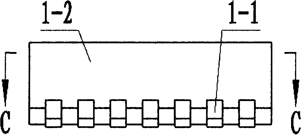
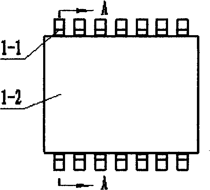
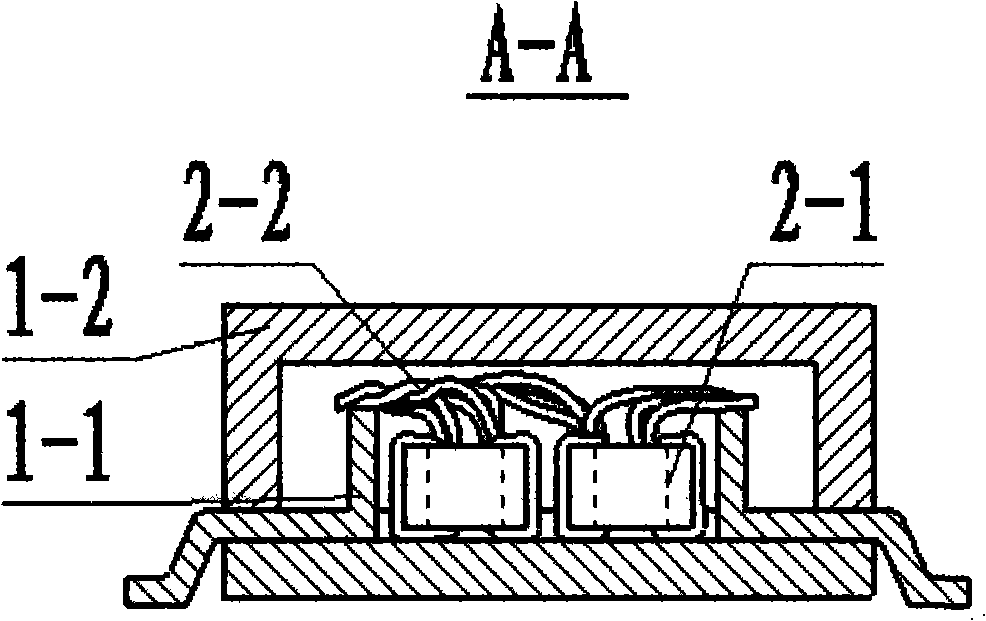
[0045] Such as Figure 6 As shown, laser welding is performed on a single network transformer. The device of the solderless laser welding method of the network transformer includes a positioning device connected to a microcomputer 6 and its signal, a laser welding device, and a shielding gas device. The positioning device includes a clamp 3. The workbench 5, the clamp 3 is embedded and fixed with the magnetic ring coil wire 2-2 of the network transformer at the lowest position of the lift, and the pin frame 1 of the network transformer is fixedly connected with the workbench 5; The above-mentioned laser welding device adopts a dynamic focusing first and then scanning method, which includes a laser 7, a beam expander 8, a dynamic focusing unit 9 and a dynamic focusing unit composed of a focusing mirror 10, an X-axis scanning galvanometer 11, a Y-axis Scanning vibrating mirror 12; described shielding gas device comprises nozzle 4 and switch mechanism thereof, described two nozzl...

Embodiment 2

[0056] Such as Figure 6 , 7 As shown, for a plurality of network transformers to perform pipeline laser welding, the laser welding device of the non-soldering material network transformer includes a positioning device connected to a microcomputer 6 and its signal, a laser welding device, and a shielding gas device. The positioning device includes Fixture 3, conveyor belt 5, the fixture 3 is embedded and fixed with the magnetic ring coil wire 2-2 of the network transformer at the lowest position of lifting, and the pin frames 1 of multiple network transformers are fixedly connected with the conveyor belt 5 in turn ; The laser welding device adopts a scanning mode after first dynamic focusing, which includes a dynamic focusing unit composed of a laser 7, a beam expander 8, a dynamic focusing unit 9 and a focusing mirror 10 connected by an optical path, an X-axis scanning galvanometer 11, The Y-axis scanning vibrating mirror 12; the shielding gas device includes a nozzle 4 and ...


PUM

PropertyMeasurementUnit
Diameteraaaaaaaaaa

Abstract

The present invention provides a solderless laser soldering method of a network transformer. The lead wire of a magnetic loop coil is wound on a clamp, so that the magnetic loop coil can be fixed in the clamp; a pin frame is fixed on a working platform; the magnetic loop coil is fixed on the pin frame; a computer controls scanning vibrating mirrors to locate a laser beam to the first pin of the pin frame, and two types of lasers are emitted in succession to fulfill the gasification of coating lacquer and a soldering operation; the laser beam is located to the next pin of the same row of the pin frame to repeat the gasification of coating lacquer and the soldering operation, and the process is repeated until all the pins are soldered; the laser beam is located to the positions nearing the outside lead wires of the clamp on soldering spots, a third type of laser is then emitted to cut off excessive lead wires which are used to fix the magnetic loop coil before soldering, and therefore a network transformer is soldered. The solderless laser soldering method, which has the advantages of high soldering speed, firmness, good appearance and no need of complex manual winding, solder and manual soldering, follows the current trend of the unleaded soldering of electronic components and can realize production line operation and mass automatic production.

Description

technical field [0001] The invention relates to a solderless laser precision welding technology, in particular to a solderless laser welding method and device for a network transformer. Background technique [0002] With the invention of computer technology and communication technology and the popularization of the Internet, network transformers have been widely used, and have become indispensable devices in the fields of computers, communications, routers, switches, power supplies and other networks and communications. The network transformer is composed of a magnetic ring coil 2, a corresponding connecting pin 1-1 of the pin frame 1 and a packaging shell 3, and the magnetic ring coil 2 is composed of an iron core 2-1 and a wire 2-2 surrounding the iron core (such as Figure 1~5 As shown), the wire 2-2 of the magnetic ring coil 2 and the connecting pin 1-1 are integrated by welding, the magnetic ring coil 2 and the connecting pin 1-1 are welded, and the plastic shell 3 is us...

Claims


Application Information

Patent Timeline
IPC IPC(8): B23K26/20B23K26/04B23K26/12B23K37/053H01F41/00B23K101/36B23K26/064B23K26/22
Inventor 杨永强吴伟辉师文庆
Owner SOUTH CHINA UNIV OF TECH
Features
  • Generate Ideas
  • Intellectual Property
  • Life Sciences
  • Materials
  • Tech Scout
  • Unparalleled Data Quality
  • Higher Quality Content
  • 60% Fewer Hallucinations
Learn More