Coal thermal decomposition grate firing apparatus and its combustion method

A technology of coal pyrolysis and pyrolysis chamber, which is applied in the field of coal pyrolysis layer combustion devices, can solve the problems of increasing the complexity of the overall equipment volume, the influence of semi-coke fluidity and fluidization, poor economy and popularization, etc., to achieve Avoid desulfurization agent deactivation, simple structure, reduce the effect of low temperature

Inactive Publication Date: 2009-02-18
INST OF PROCESS ENG CHINESE ACAD OF SCI
View PDF1 Cites 20 Cited by
  • Summary
  • Abstract
  • Description
  • Claims
  • Application Information

AI Technical Summary

Problems solved by technology

However, since the fluidized bed pyrolysis furnace provided by this patent is located outside the hearth of the layer-fired furnace, the structure of the connecting conveying channel has a great influence on the fluidity of the semi-coke and the fluidization of the fuel in the fluidized bed. It is difficult to match with the combustion in the floor-burning furnace, especially for small-capacity floor-burning furnaces, the impact is more prominent
In addition, setting an external fluidized bed pyrolysis chamber will increase the volume and complexity of the overall equipment, so the economy and popularization of this patented technology are poor

Method used


Image

  • Coal thermal decomposition grate firing apparatus and its combustion method
  • Coal thermal decomposition grate firing apparatus and its combustion method
  • Coal thermal decomposition grate firing apparatus and its combustion method

Examples


Embodiment 1

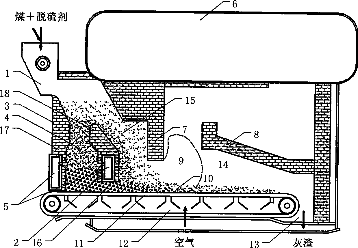
[0042] The coal pyrolysis layer combustion device of the present embodiment is as figure 1As shown, it includes: a layer of combustion furnace body 3, the interior of the furnace body 3 is divided into an upstream oxidation pyrolysis chamber 4 and a downstream layer combustion chamber 14 by a partition wall 2, and the oxidation pyrolysis chamber 4 is located at the front section of the mechanical grate 11 Above, it communicates with the layer combustion chamber 14 through the upper communication port 15 and the lower communication port 16, and the lower part of the oxidation pyrolysis chamber 4 is provided with an air supply device 5 arranged in the double-sided wall, and the air supply device 5 is respectively arranged in front of the layer combustion furnace. Two in-wall air chambers in the wall 17 and the partition wall 2 form. The partition wall 2 is provided with a reduced diameter 18 above the air supply device 5 to enhance the gas-solid mixing effect in the oxidation py...

Embodiment 2

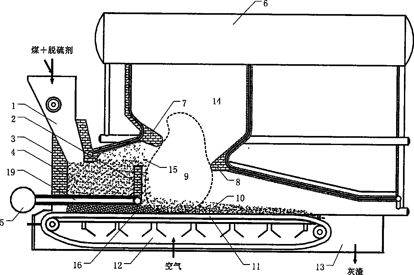
[0049] The coal pyrolysis layer combustion equipment of this embodiment is as figure 2 As shown, it includes a furnace body 3 and a hopper 1, the bottom of the furnace body 3 is provided with a mechanical fire grate 11 and an air chamber 12, the rear section of the fire grate 11 is covered with a semi-coke layer 10, and the inside of the furnace body 3 is covered by a partition wall 2 is divided into an oxidation pyrolysis chamber 4 and a layer combustion chamber 14, the lower part of the hopper 1 communicates with the oxidation pyrolysis chamber 4, and the oxidation pyrolysis chamber 4 communicates with the layer through the upper communication port 15 and the lower communication port 16 Combustion chamber 14 communicates, is provided with front arch 7 near described upper communication port 15 in layer combustion chamber 14, and described front arch 7 becomes 45 ° with horizontal direction, and also is provided with and horizontal direction in layer combustion chamber 14 and...

Embodiment 3

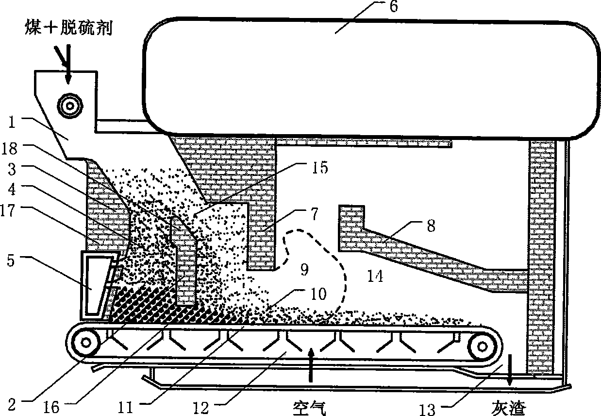
[0051] The oxidation pyrolysis chamber 4 of the coal pyrolysis layer combustion equipment of the present embodiment is a fixed bed, adopts the air supply device 5 arranged in the single wall, such as image 3 As shown, the air supply device 5 is composed of an in-wall air chamber arranged in the front wall 17 of the layered combustion furnace, and other structures are the same as in Embodiment 1. The air supply device arranged in a single wall is suitable for smaller-scale layer-fired furnaces, and has a simple structure. During the combustion process, the smaller semi-coke particles and combustible gas generated by the pyrolysis of coal in the oxidation pyrolysis chamber overflow from the upper communication port 15 or are entrained by the air flow into the layer combustion chamber 14, while the generated large-size semi-coke particles pass through The peroxidation pyrolysis chamber falls behind the front section of the mechanical grate 11 below, and along with the movement o...


PUM


Abstract

The invention relates to a coal pyrolysis layer combustion device and the combustion method thereof, including that the furnace body interior of the first layer combustion furnace is divided into an upper oxidation pyrolysis chamber and a lower fire grate layer combustion chamber which is communicated with each other; the coal and desulfurizer are mixed to be fed into the middle part of the oxidation pyrolysis for oxidation pyrolysis through a hopper; the generated combustible gas and the smaller semi-coke particles are overflowed through the upper-connected through port or are carried in the airflow to be fed into the mechanical fire grate layer combustion chamber; the bigger semi-coke particles fall on the mechanical fire grate and are fed into the layer combustion layer for combustion; the mechanical fire grate layer combustion chamber is provided with a front arch and a back arch for organizing the airflow field inside the furnace; the coal pyrolysis layer combustion device and the combustion method thereof adopt the fluidization characteristics of the coal particles with different particle diameters and the high thermal capacity characteristic inside the oxidation pyrolysis chamber to realize the natural separation of the coal particles with different particle diameters and the rapid oxidation pyrolysis of coal, reduce the fire grate coal leakage loss and the incomplete combustion loss caused by the front segment low temperature of the fire grate and reduce the emission of the SOx and NOx pollutant through the combination of the pyrolysis desulfurization and the combustion desulfurization, and the reburning denitration formed by the coal pyrolysis product.

Description

technical field [0001] The invention belongs to the technical field of clean energy, and in particular relates to a coal pyrolysis layer combustion device and a combustion method thereof which can improve the combustion efficiency of a coal-fired industrial boiler and realize smokeless, low nitrogen oxide and sulfur oxide emissions. Background technique [0002] my country is rich in coal resources. In 2004, the proven coal reserves were 114.5 billion tons, accounting for about 87.4% of the proven reserves of conventional energy. The characteristics of "lack of oil, less gas, and rich coal" in my country's energy distribution and the low price of coal lead to the dominant position of coal in my country's energy consumption structure, and for a long period of time in the future, the basis of coal Energy status will not be shaken. There are about 530,000 coal-fired industrial boilers in my country, and their annual coal consumption accounts for about 1 / 3 of my country's annual...

Claims


Application Information

Patent Timeline
Patent Type & Authority Applications(China)
IPC IPC(8): F23B10/00F23B101/00F23B10/02
Inventor 许光文郝江平高士秋董利刘新华
Owner INST OF PROCESS ENG CHINESE ACAD OF SCI
Why Eureka
Try Eureka