Plunger chip die for processing magnetic material and manufacture method thereof

A magnetic material and mold manufacturing technology, which is applied in the direction of manufacturing tools, metal processing equipment, welding/cutting media/materials, etc., can solve problems such as affecting blanks, easy deformation of punches, and short service life of punches, so as to improve the surface Hardness, reducing punch deformation, and solving the effect of sticking mold problems

Active Publication Date: 2009-03-11
德昌电机(南京)有限公司
View PDF0 Cites 9 Cited by
  • Summary
  • Abstract
  • Description
  • Claims
  • Application Information

AI Technical Summary

Problems solved by technology

[0003] The requirements of this technology are simple, but many deficiencies are found in the process of production and application. The main problems are that the surface of the punch often sticks to the mold, and the cleaning is troublesome and the cleaning frequency is high; the punch is easily deformed, which affects the formed blank and affects Product qualification rate; the magnetic force line is not clear, which is easy to cause product cracking; the service life of the punch is very short, the wear is fast, and the average life is 150,000 to 200,000 times; due to the high failure rate, the maintenance cost is high during use

Method used


Image

  • Plunger chip die for processing magnetic material and manufacture method thereof
  • Plunger chip die for processing magnetic material and manufacture method thereof
  • Plunger chip die for processing magnetic material and manufacture method thereof

Examples


example 1

[0041] Example 1, using 45# steel as the parent material

[0042] Proceed as follows:

[0043] 1) Take 45# steel for tempering and quenching treatment:

[0044] Put 45# steel in a box-type resistance furnace, raise the temperature of the resistance furnace to about 830°C within 2 hours, and keep it warm for about 30 minutes;

[0045] The material is taken out, quenched with brine with a mass percentage concentration of 15%, and the material is naturally cooled in the brine;

[0046] 2) According to the mold drawing and the design of the magnetic force line, the obtained material is made into a matrix of the required shape and size;

[0047] 3) Use a cloth wheel to polish the surface to be welded of the parent body to remove oil and oxide layer, and the surface is required to be as bright as new;

[0048] 4) Adopt spray welding process to process non-magnetic layer:

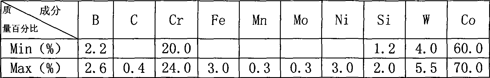
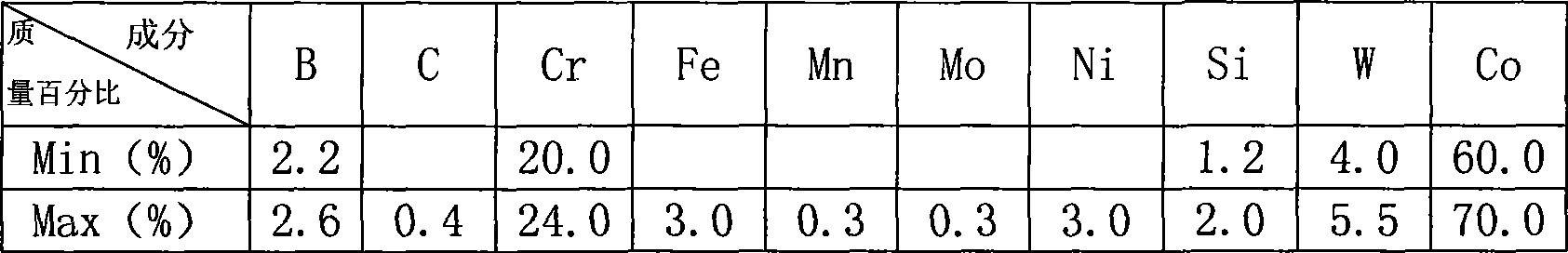
[0049] First use a welding torch to heat the surface of the parent body to be welded until it turns red, an...

example 2

[0055] Example 2, using T8 steel as the parent material

[0056] Proceed as follows:

[0057] 1) Take T8 steel for tempering and quenching treatment:

[0058] Put T8 steel in a well-type resistance furnace, raise the temperature of the resistance furnace to about 840°C within 2.2 hours, and keep it warm for about 28 minutes;

[0059] The material is taken out, quenched with brine with a mass percentage concentration of 17%, and placed in the brine to cool naturally;

[0060] 2) According to the mold drawing and the design of the magnetic force line, the obtained material is made into a matrix of the required shape and size;

[0061] 3) Use a cloth wheel to polish the surface to be welded of the parent body to remove oil and oxide layer, and the surface is required to be as bright as new;

[0062] 4) Using spray welding process to process non-magnetic layer:

[0063] First use a welding torch to heat the surface of the parent body to be welded until it turns red, and then spr...

example 3

[0069] Example 3, using T10 steel as the parent material

[0070] Proceed as follows:

[0071] 1) Take T10 steel for tempering and quenching treatment:

[0072] Put T10 steel in a box-type resistance furnace, raise the temperature of the resistance furnace to about 820°C within 1.8 hours, and keep it warm for about 33 minutes;

[0073] The material is taken out, quenched with brine with a mass percentage concentration of 14%, and the material is placed in brine to cool naturally;

[0074] 2) According to the mold drawing and the design of the magnetic force line, the obtained material is made into a matrix of the required shape and size;

[0075] 3) Use a cloth wheel to polish the surface to be welded of the parent body to remove oil and oxide layer, and the surface is required to be as bright as new;

[0076] 4) Using spray welding process to process non-magnetic layer:

[0077] First use a welding torch to heat the surface of the parent body to be welded until it turns r...


PUM

PropertyMeasurementUnit
microhardnessaaaaaaaaaa
friction coefficientaaaaaaaaaa

Abstract

The invention relates to a punch mould for processing magnetic materials, which comprises a parent body, a non-conducting magnet layer which is arranged on the parent body. The non-conducting layer uses alloy material; the surface of the non-conducting layer is provided with a DLC coat. The processing method of the mould comprises the steps: 1) the materials of the parent body carry out the quenching and tempering treatment; 2) according to the drawing paper of the mould and the design of the magnetic line of force, the materials of the parent body are made into the parent body with the needed shape and size; 3) the welding face of the parent body to be treated is removed with oil and oxidizing layers; 4) by adopting a spray welding technique, the non-conducting layer is processed; 5) according to the size of the mould, the machining is carried out; according to the drawing paper and the size of the mould cavity, the assembly manufacturing are carried out; 6) polishing treatment is carried out on the surface of the punch; 7) the non-conducting magnet layer of the punch adopts the DLC spray finishing treatment. The mould solves the problems that in the existing technology, the surface of the punch often has mold sticking; the punch is easily deformed; the magnet line of force is not clear and the service life of the punch is short.

Description

technical field [0001] The invention belongs to the technical field of magnetic material manufacturing, in particular to a punch die for processing magnetic materials and a manufacturing method thereof. This technology is applicable to the magnetic field orientation forming link of permanent ferrite magnetic materials. Background technique [0002] In the manufacture of magnetic materials, one of the molds——the punch manufacturing technology is very mature. Generally, the bottom is made of 45# steel, and the surface is made of stainless steel with argon or oxygen welding and polishing. The structure of the punch is generally that the parent body is made of 45# steel, and the non-magnetic layer is welded on the parent body by non-magnetic stainless steel. [0003] The requirements of this technology are simple, but many deficiencies are found in the process of production and application. The main problems are that the surface of the punch often sticks to the mold, and the cl...

Claims


Application Information

Patent Timeline
Patent Type & Authority Applications(China)
IPC IPC(8): B30B15/02B23P15/00B23K5/18B23K35/30
Inventor 徐建国
Owner 德昌电机(南京)有限公司
Why Eureka
Try Eureka