
Optical power measurement method

A measurement method and technology of optical power, applied in the direction of using electric radiation detectors for photometry, etc., can solve the problems of complex calculation formula and correction of optical power value and low precision.

Inactive Publication Date: 2009-06-10
XIDIAN UNIV
View PDF0 Cites 8 Cited by
  • Summary
  • Abstract
  • Description
  • Claims
  • Application Information

AI Technical Summary

Problems solved by technology

[0004] The purpose of the present invention is to overcome the defects of complex optical power value calculation formula and correction and low precision in the existing measurement method, and propose an optical power measurement method combining a logarithmic ratio amplifier circuit and a software algorithm

Method used


Image

  • Optical power measurement method
  • Optical power measurement method
  • Optical power measurement method

Examples


Embodiment Construction

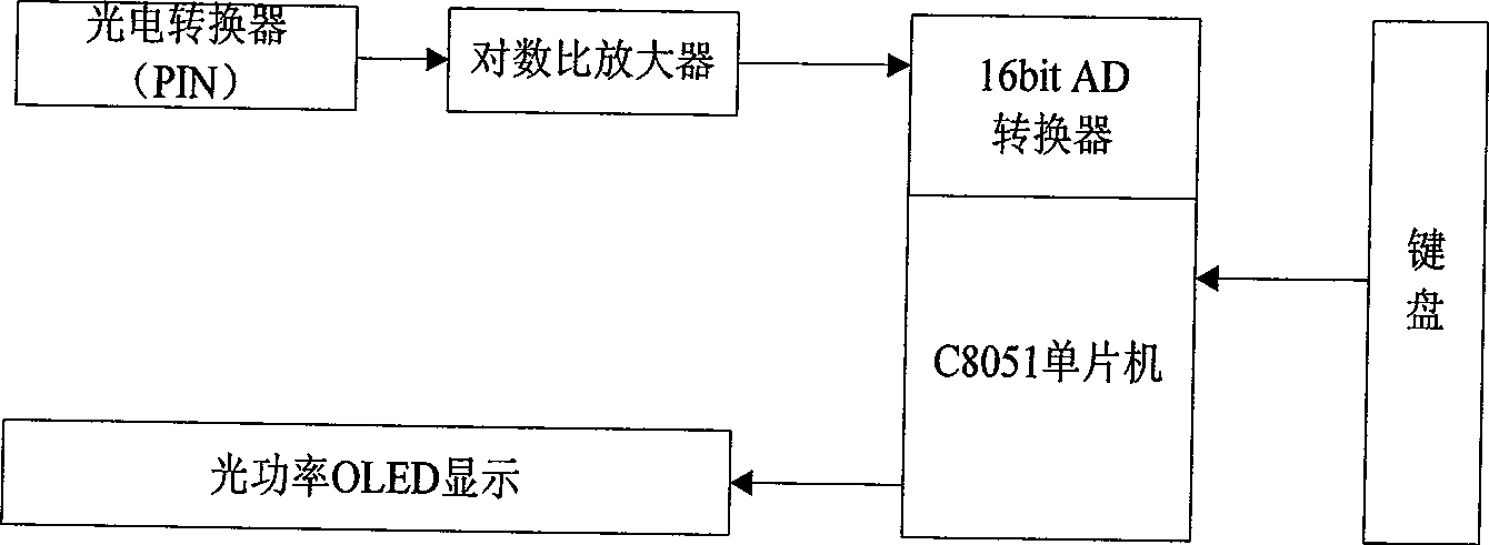
[0050] refer to figure 2 , is the test system of the present invention, which mainly includes a photoelectric converter, a logarithmic ratio amplifier, a C8051 single-chip microcomputer embedded with 16bit AD conversion, an optical power OLED display and a keyboard. in:

[0051] The photoelectric converter is a PIN photodiode, which covers the entire wavelength range of 0.65 ~ 1.65 μm commonly used in optical power measurement. It has the advantages of fast response speed and small temperature influence. The conversion of optical signal to current signal is completed through the photodiode. Table 1 shows the responsivity of photodiodes at 25°C.

[0052] Table 1 Responsivity of photodiodes

[0053]

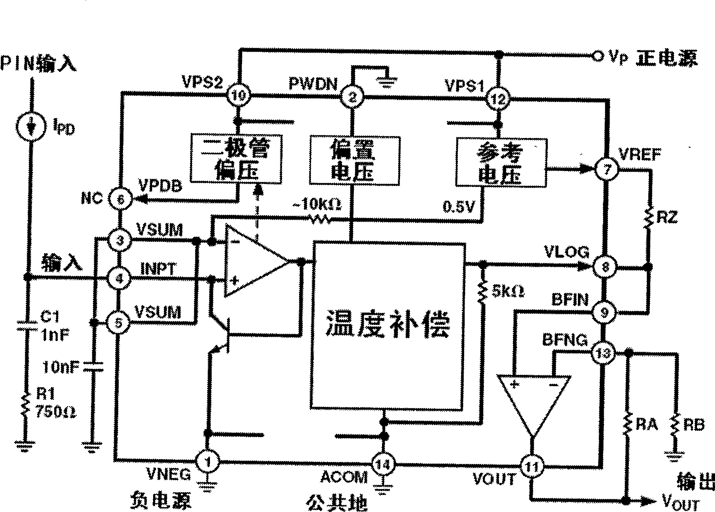
[0054]The logarithmic ratio amplifier, whose operating voltage is 3-5.5V, is a logarithmic ratio amplifier with a large dynamic range, including a photodiode interface, a logarithmic ratio amplifier circuit, a temperature compensation circuit, and a linear amplifier circuit. ...


PUM


Abstract

The invention discloses a light power measuring method with a log ratio amplifying circuit combined with software. Measuring process is: constructing light power calculating formula P=K<3>beta+C<3> according to the log ratio amplifying circuit in the measuring system; configuring an AD converter according to wavelength of measured light source; connecting the measured light source with the light end, picking a signal received at the light end, the AD converter reading in data N times circularly after photoelectric conversion and log amplification, solving an average value beta of N conversion values; judging whether value of beta exceeds measuring range, if so, measurement is over; if not, dividing the light source measured according to power of the standard light source; comparing beta value with an edge value of the standard light source, selecting corresponding K<3> and C<3> according to location where beta is; introducing determined beta, K<3> and C<3> values to the light power calculating formula to obtain a power value P of the measured signal. The invention, compared with current power measuring method, is simple in process, large in dynamic range, and high in precision for light power measurement of optical fiber communication.

Description

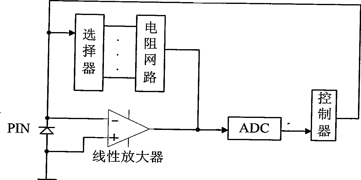
technical field [0001] The invention belongs to the field of optical fiber communication measurement, in particular to a method for measuring optical power, which can be used in optical power meter measuring instruments. Background technique [0002] The principle of general optical power meter measurement is as follows: figure 1 Shown: The light detection diode PIN completes the conversion of optical signal to electrical signal, that is, when the measured light is irradiated on PIN, the input optical signal is converted into the corresponding electrical signal; since the input electrical signal is very weak, it is completed by a linear amplifier The electrical signal is amplified; the analog-to-digital converter ADC converts the electrical signal into a digital signal, which is convenient for digital processing and calculation of optical power values; the controller switches the optical power measurement range by selecting different resistance values. [0003] Usually, opt...

Claims


Application Information

Patent Timeline
Patent Type & Authority Applications(China)
IPC IPC(8): G01J1/42
Inventor 郭万里李兵兵孟波岳攀沈晓菲
Owner XIDIAN UNIV
Learn More