Three light wave transversal shearing interference apparatus and method for extracting differential phase

A technology of transverse shearing and differential phase, which is applied in the device of three-wave transverse shearing interference, extracts the field of differential phase, and can solve the problems of difficult to play spatial light modulator, vibration of optical system, low control precision, etc., and achieve environmental interference Effects of insensitivity, low coherence requirements, and high regulation precision

Inactive Publication Date: 2009-06-10
NANJING UNIV
View PDF0 Cites 27 Cited by
  • Summary
  • Abstract
  • Description
  • Claims
  • Application Information

AI Technical Summary

Problems solved by technology

[0010] In the researches mentioned above, there are many ways to realize the shearing interference of two beams of light, but it is difficult to flexibly control the amount of shearing and phase shift at the same time, the control accuracy is low, and generally requires the mechanical Movement, easy to cause vibration of the optical sy...

Method used


Image

  • Three light wave transversal shearing interference apparatus and method for extracting differential phase
  • Three light wave transversal shearing interference apparatus and method for extracting differential phase
  • Three light wave transversal shearing interference apparatus and method for extracting differential phase

Examples


Embodiment 1

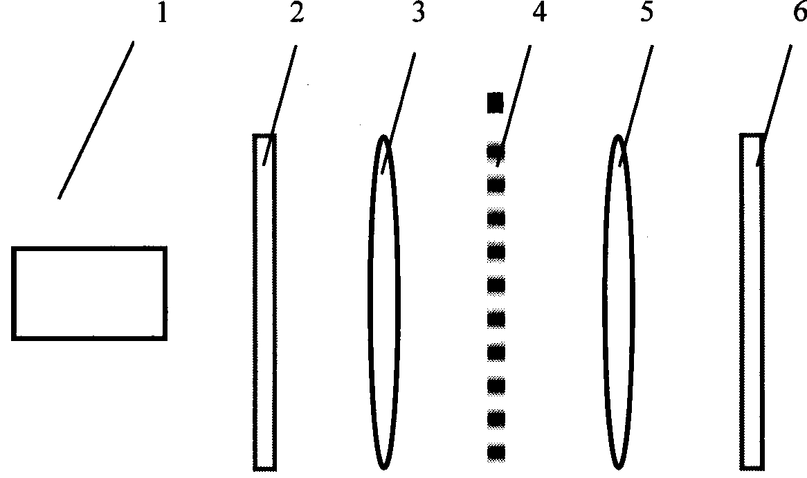
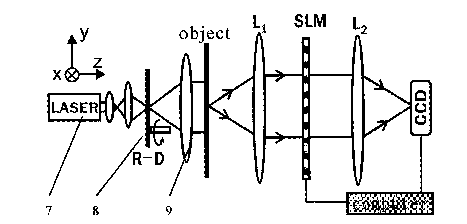
[0030] Such as figure 2 As shown, the complete technical scheme of the three-wave dynamic transverse shearing interference generating device of the present invention is as follows: the light source we use is a He-Ne laser 7 with a wavelength of 632.8 nm, and the spatial light modulator 4 is a transmissive liquid crystal from Sony. The spatial light modulator has a number of pixels of 1024×768 and a pixel size of 18 microns x 18 microns. A piece of rotating ground glass 8 is located on the front focal plane of the lens 9 to reduce the spatial coherence of the illumination light wave so as to reduce the effect of speckle. The plane light wave generated by the lens 9 illuminates the object to be measured, the confocal lenses L1 and L2 form a 4f system, and the spatial light modulator (SLM) is placed on the confocal surface of the 4f system. The computer is connected to the spatial light modulator and the charge coupled device (CCD) at the same time, which can control the display of ...

Embodiment 2

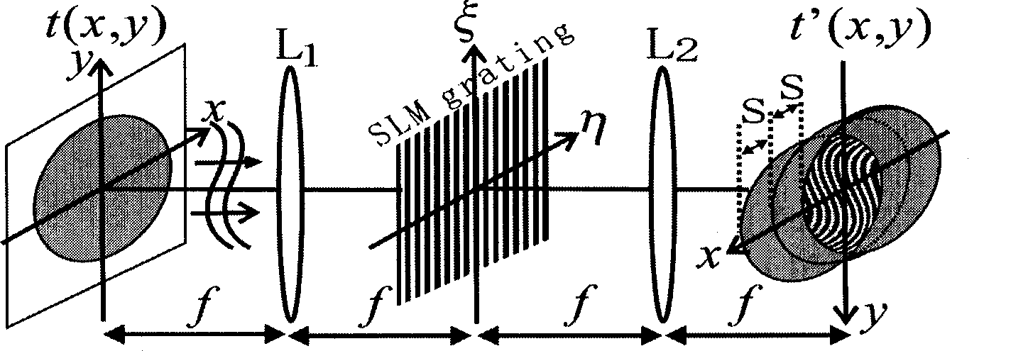
[0035] according to figure 1 The principle is to build a 4f optical system, and the specific experimental system built based on this is such as figure 2 Shown. In order to verify the effect of generating three light waves, we add a small light hole on the object plane. The experimental effects of three beams of light generated when the grating line direction is along the y direction and the x direction are respectively provided without grating, and the image is collected by CCD. Figure 4 The first column in the middle shows the grating loaded on the spatial light modulator. When the grating is not added, after two Fourier transforms, it is still an image of a small hole spot. Figure 4 The second column in the middle shows the output effect after loading the grating, forming three staggered light spots in the x direction and y direction.

Embodiment 3

[0037] according to figure 1 Build a 4f optical system, and build a specific experimental system based on it such as figure 2 Shown. A test lens is placed on the input surface of the 4f system to generate the phase distribution of the spherical wavefront to be measured. The display on the spatial light modulator is as follows Figure 5 For the two gratings shown in the first column, the three-wave transverse shearing interference pattern with the shearing direction along the x direction and the y direction is observed on the output surface, as Figure 5 As shown in the second column.


PUM


Abstract

The invention provides a device of a tri-light wave for transverse clipping interference and a method for extracting the difference phase. The device comprises a light source, a to-be measured object, a first lens, a space light modulator, a second lens and a charge coupled device; the to-be measured object is located on the focus plane of the first lens; the base focus plane of the first lens; the space light modulator is located at the front focus plane of the second lens; the charge coupled device is located on the back focus plane of the second lens; the light source, the to-be measured object, the first lens, a space light modulator and the second lens and a charge coupled device form the coaxial device. The invention uses the calculating a spatial light modulator on the cosine of the computer-generated hologram grating to control the +- 1-ordered diffraction light of the relative phase shift of zero level and the shear volume, you can generate real-time dynamic shear interferogram phase-shifting, interference by Figure intensity calculated differential phase calculation. The present invention has a simple, compact structure, high precision control, dynamic control and so on.

Description

Technical field [0001] The invention relates to an optical interference device, in particular to a device for three-wave lateral shearing interference and a method for extracting a differential phase. Background technique [0002] The optical test method has the characteristics of non-contact and high sensitivity, and is the main method in the field of metrological test technology. Among the optical testing methods, optical interferometry is a precision measurement technique that can be accurate to the order of one hundredth of the wavelength, and the transverse shear interference method among them has low requirements for light source coherence and strong anti-interference ability. The advantages have received widespread attention. The optical system that realizes transverse shearing interference includes Mach-Zehnder transverse shearing interferometer, polarized light transverse shearing interferometer, double grating transverse shearing interferometer, etc. People usually use ...

Claims


Application Information

Patent Timeline
IPC IPC(8): G01J9/02
Inventor 丁剑平翟思洪陈璟樊亚仙王慧田
Owner NANJING UNIV
Why Eureka
Try Eureka