
Electric motor for built-in recycling compressor

A circulating compressor, built-in technology, applied in the field of electric motors, can solve the problems of reducing ground resistance, wasting energy, poor contact, etc., to achieve the effect of eliminating oil and air, simple connection structure, and preventing phase-to-phase heating

Inactive Publication Date: 2009-06-10
湘潭金阳电机泵业有限公司
View PDF0 Cites 1 Cited by
  • Summary
  • Abstract
  • Description
  • Claims
  • Application Information

AI Technical Summary

Problems solved by technology

[0003] However, there are still some deficiencies in the above-mentioned motors for built-in circulating compressors, which seriously affect the normal operation and service life of the motors: if the motor windings and coil structures and manufacturing processes are unreasonable and affect the service life of the motors, the motor rotors need to be less than The 1.6mm axial movement and high coaxiality and concentricity requirements affect the normal operation of the motor
The unreasonable performance of the motor winding and coil structure and the manufacturing process is as follows: First, the insulation layer of the motor coil winding is made by the process of casing first and then forming. It is easy to break the casing during winding, which will damage the insulation layer of the winding and reduce the ground resistance; secondly, the circular casing is used as the insulating layer, which reduces the sealing performance of the coil, and there is a gap between the circular casing and the rectangular winding. The cavity that is easy to accumulate greasy and dirt will also seriously reduce the ground resistance; thirdly, there are no connectors and isolation spacing between windings, between windings and coils, and between upper windings and lower windings. There is no heat dissipation space and safe isolation distance between phases and turns, which will easily cause the insulation resistance between phases and turns to be zero and burn the motor; moreover, the insulation layer of the coil winding is made of circular F4 tubes, resulting in inconvenient maintenance and repair; Fourth, the connection of the winding ends is soldered, and the soldered seam has the following disadvantages: ①The welded seam is not firmly welded. When the motor is started, it is easy to loose the welding due to the strong impact of the starting current, causing the motor to burn; ② Insufficient welding of the weld seam reduces the contact area of ​​the coil winding connector, resulting in poor contact, heat generation, and desoldering, resulting in the final burning of the motor; ③The weld seam has poor high temperature resistance and unbalanced three-phase DC resistance, causing other equipment to operate unstable , the traditional treatment method is to use a large transformer to match the motor, resulting in a waste of energy and an increase in cost; fifth, the motor housing is long, the machining error is large, and the axial movement and coaxiality and concentricity cannot meet the operating requirements. Requirements; while the axial movement of the motor rotor and the higher coaxiality and concentricity requirements are manifested in the fact that when the motor is working, it is necessary to select a suitable bearing for the motor when the turbo compressor is running, so that there is a small amount of axial movement of the motor shaft. When coupling, it must be connected according to the magnetic field center parameters when the motor is detected.
So far, the aforementioned defects will seriously affect the service life and production efficiency of the motor

Method used

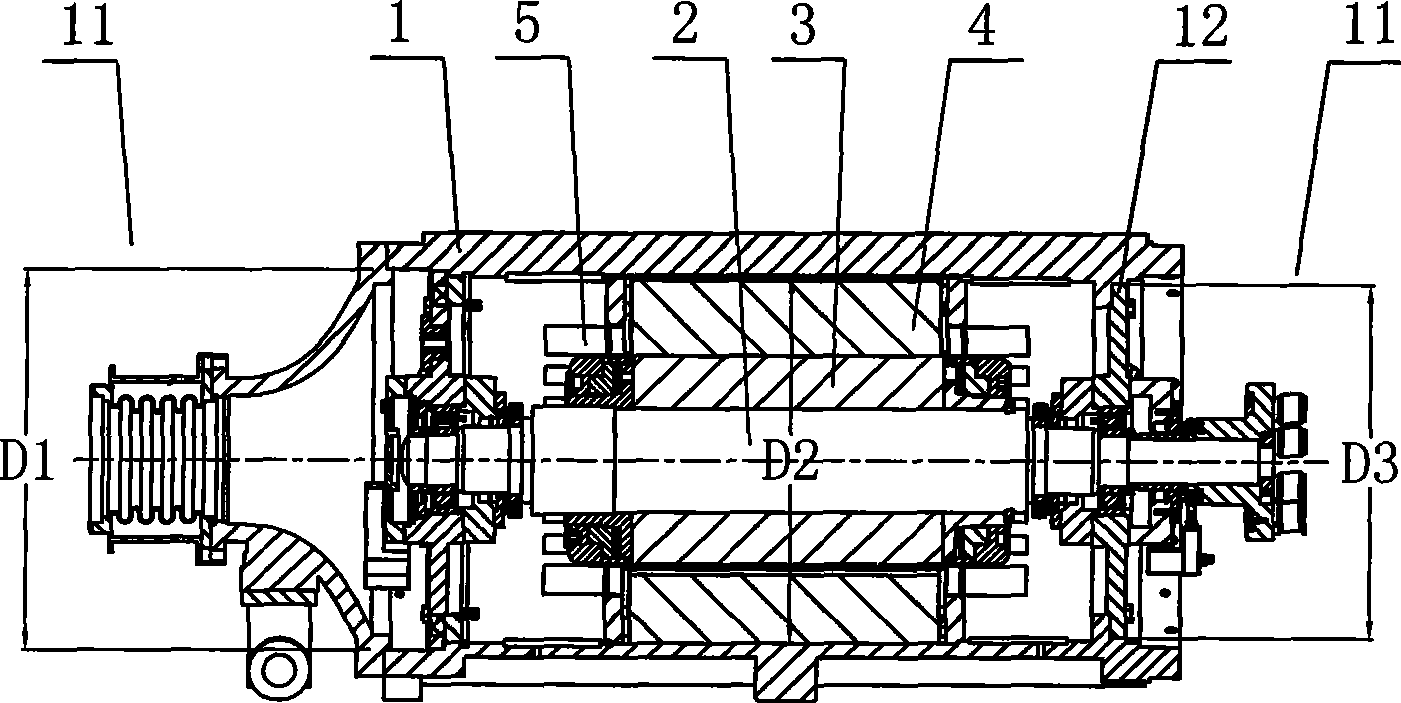
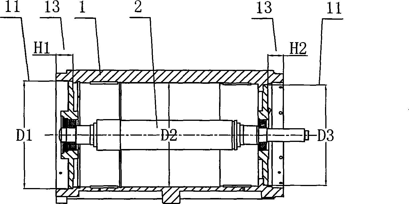
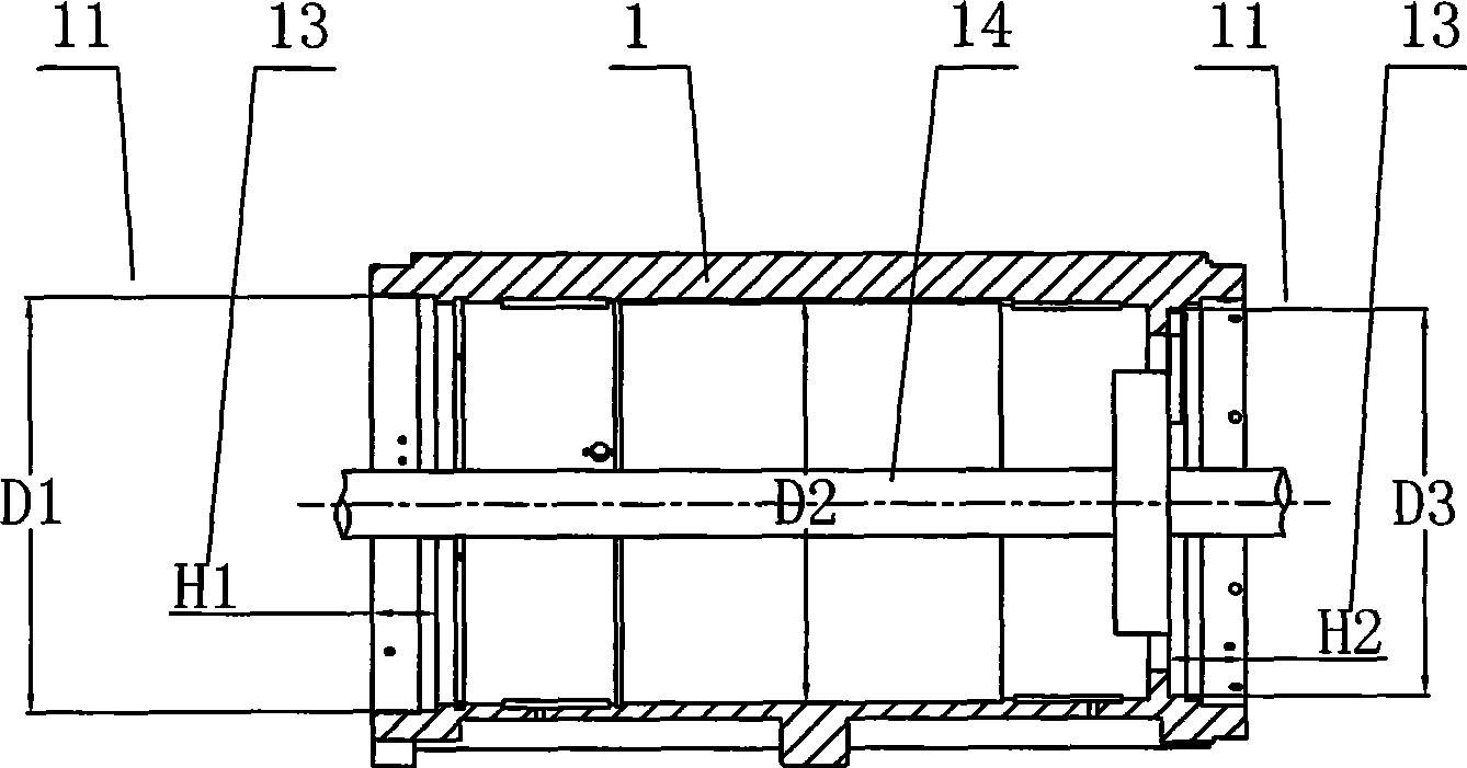

Image

  • Electric motor for built-in recycling compressor
  • Electric motor for built-in recycling compressor
  • Electric motor for built-in recycling compressor

Examples


Embodiment Construction

[0029] Referring to the accompanying drawings, a motor for a built-in circulating compressor mainly includes a housing 1, a rotating shaft 2, a rotor core 3, a stator core 4 and a coil 5, especially between the upper and lower windings 6 of the coil 5. Connectors 7 and isolation spacing S8 are provided at the connection. After the side ends of the winding 6 are connected and fixed with the connector 7, the isolation distance S between the upper and lower layers of the coils 5 embedded in the magnetic slot of the stator core 4 naturally forms an annular spacing area centered on the rotating shaft. The separation distance S is 8-15mm, and the determination of the size of S is related to the pitch setting of the stator winding. The annular space area enables a heat dissipation space between the upper and lower windings 6 of the coil 5, and makes the connection structure of the winding 6 simpler, more scientific and effective. Prevent the occurrence of motor phase heating, short c...


PUM


Abstract

The invention relates to an electromotor for a built-in recycle compressor. The electromotor mainly comprises a shell, a rotating shaft, a rotor core, a stator core and a coil; a connecting part between an upper-layer winding and a lower-layer winding of the coil is provided with a connector and isolated spacing S. The electromotor adopts the technical proposal of arranging the connector and the isolated spacing S in the connecting part between the upper-layer winding and the lower-layer winding, using argon-arc welding and adopting a boring bar cutter to machine each matched hole and each axial end face of the shell; and the electromotor overcomes the disadvantages that the prior electromotor for the built-in recycle compressor has short service life, poor operation stability, low production efficiency and inconvenient maintenance and repairing. The electromotor is suitable for equipment in production of chemical engineering industry, in particular an enterprise producing 180,000 tons of synthetic ammonia and 300,000 tons of urea.

Description

technical field [0001] The invention relates to a motor, in particular to a motor for a built-in circulation compressor. Background technique [0002] The existing built-in circulating compressor motor is a three-phase AC squirrel-cage induction motor, which is characterized by being thin and long, which is convenient for direct connection with the turbine compressor and convenient for use in a high-pressure cylinder; the surface of the shell has a cooling Ribs are used to dissipate the heat of the motor; the lubrication method of the motor bearing is to inject oil from the oil injection pump outside the high-pressure cylinder and the timing oil discharge system to complete the lubrication of the motor bearing; the motor also uses dryers, electric heaters, etc. To dry motor protection gas and auxiliary equipment for silica gel regeneration. [0003] However, there are still some deficiencies in the above-mentioned motors for built-in circulating compressors, which seriously...

Claims


Application Information

Patent Timeline
IPC IPC(8): H02K3/04H02K3/28H02K5/22H02K15/14
Inventor 郭正华
Owner 湘潭金阳电机泵业有限公司
Learn More