
Photoresist silicification method and method for forming photoresist mask pattern

A photoresist mask and photoresist technology, which is applied in the field of integrated circuit manufacturing, can solve the problems of prolonging the process cycle and increasing process costs, and achieve the effects of reducing thickness, saving material costs, and reducing energy

Inactive Publication Date: 2009-06-17
SEMICON MFG INT (SHANGHAI) CORP
View PDF1 Cites 2 Cited by
  • Summary
  • Abstract
  • Description
  • Claims
  • Application Information

AI Technical Summary

Problems solved by technology

This also increases the process cost and prolongs the process cycle

Method used


Image

  • Photoresist silicification method and method for forming photoresist mask pattern
  • Photoresist silicification method and method for forming photoresist mask pattern
  • Photoresist silicification method and method for forming photoresist mask pattern

Examples


Embodiment Construction

[0031] The photoresist silicidation method and the method for forming a photoresist mask pattern provided in the following specific embodiments and examples, adopt the silicidation method to process the photoresist mask, which improves the strength of the photoresist, so that the photoresist can be reduced. The thickness of the glue can save material cost; because the thickness of the photoresist is reduced, the energy required for exposure is correspondingly reduced, so the exposure time can be shortened and the photolithography efficiency can be improved.

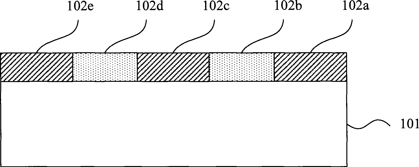
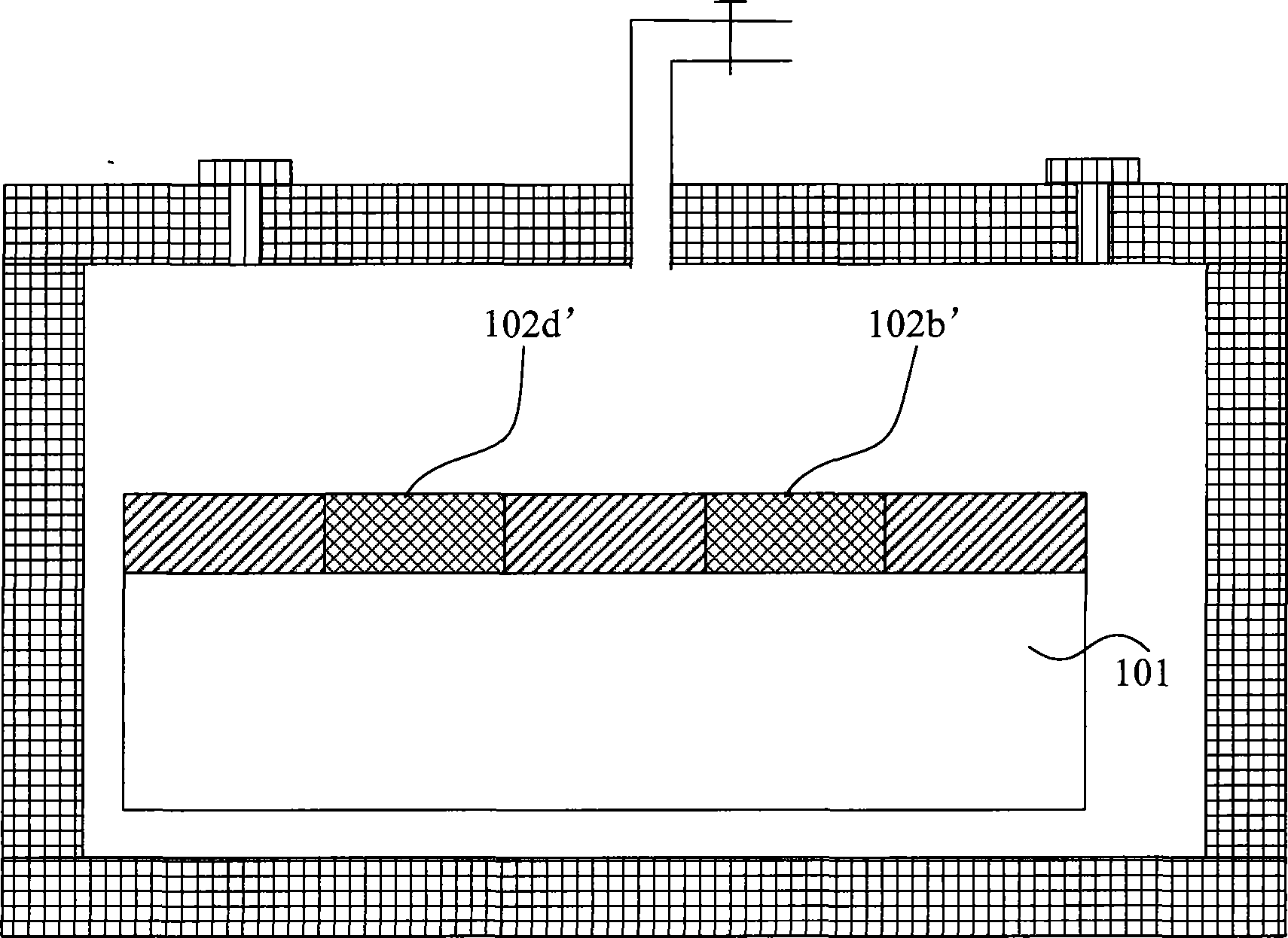
[0032] The specific implementation manners of the present invention will be described below in conjunction with the accompanying drawings.

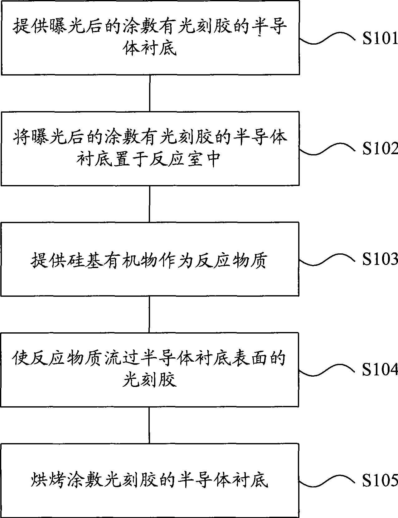
[0033] attached figure 1 The process flow chart of the specific embodiment of the photoresist silicidation method provided by the present invention includes the following steps: step S101, providing a semiconductor substrate coated with photoresist after exposure; step S102, applying...


PUM

PropertyMeasurementUnit
thicknessaaaaaaaaaa
thicknessaaaaaaaaaa

Abstract

The invention relates to a method for silicifying photosensitive resist, which comprises: providing an exposed semiconductor substrate with the surface coated with the photosensitive resist; placing the exposed semiconductor substrate coated with the photosensitive resist into a reaction chamber; providing reaction material comprising a silicon-based organic substance, and causing the reaction material to flow through the photosensitive resist on the surface of the semiconductor substrate. The invention also provides a method for forming a mask pattern of the photosensitive resist. The technical proposal has the following advantages: as the silicifying process is adopted to treat a mask of the photosensitive resist, the method improves the strength of the photosensitive resist, so as to reduce the thickness of the photosensitive resist and save the cost of materials; and as the thickness of the photosensitive resist is reduced, the energy required by exposure is correspondingly reduced, so as to shorten exposure time and improve photoetching efficiency.

Description

technical field [0001] The invention relates to the field of integrated circuit manufacturing, in particular to a photoresist silicidation method and a method for forming a photoresist mask pattern. Background technique [0002] Photolithography is one of the key technologies in the field of integrated circuit manufacturing. Factors such as the accuracy of mask patterns, the speed of lithography, and the cost of lithography all affect the final quality and manufacturing cost of integrated circuits. Therefore, the improvement of the photolithography process is always a hot issue in the field of integrated circuit manufacturing. [0003] In a semiconductor process, a photoresist mask pattern is used as a barrier layer in an etching process, a barrier layer in an ion implantation process, or a protective layer in a wafer package, and the like. The thickness of the photoresist directly affects the ability of the photoresist mask pattern to protect the chip in subsequent steps....

Claims


Application Information

Patent Timeline
Patent Type & Authority Applications(China)
IPC IPC(8): G03F7/26G03F1/00G03F7/20
Inventor 崔彰日李冬
Owner SEMICON MFG INT (SHANGHAI) CORP
Learn More