Fin-and-tube type heat exchanger, and its return bend pipe

An elbow tube, heat exchanger technology, applied in indirect heat exchangers, heat exchanger shells, heat exchanger types, etc., can solve the problem of reduced evaporation performance, difficulty in maintaining swirl flow, heat transfer performance of heat exchangers, and evaporation performance. Reduce and other problems to achieve the effect of improving evaporation performance and improving reliability

Active Publication Date: 2009-06-24
KOBELCO & MATERIALS COPPER TUBE LTD
View PDF9 Cites 6 Cited by
  • Summary
  • Abstract
  • Description
  • Claims
  • Application Information

AI Technical Summary

Problems solved by technology

However, since the inner surface of the U-shaped elbow tube is smooth, it is difficult to maintain the swirling flow on the outlet side, and at the bend of the U-shaped elbow tube, water droplets (refrigerant liquid film) are sprayed, and the liquid film unstable flow
Therefore, there is a problem that after flowing into the return bend pipe of the next stage, the refrigerant is wasted in order to give the refrigerant a swirling flow again for a while, and in this region, the flow of the refrigerant is unstable, and a thick liquid film of the refrigerant is also formed. part, therefore, the thermal conductivity inside the tube tends to decrease, and sufficient evaporation performance cannot be obtained
Therefore, since the pressure loss of the refrigerant circulating inside the heat exchanger increases, the flow rate of the refrigerant decreases. Therefore, on the contrary, there is a problem that the heat transfer performance of the heat exchanger, especially the evaporation performance is significantly reduced.
[0011] Furthermore, as in Patent Document 3, when the pipe wall thickness is increased in consideration o

Method used


Image

  • Fin-and-tube type heat exchanger, and its return bend pipe
  • Fin-and-tube type heat exchanger, and its return bend pipe
  • Fin-and-tube type heat exchanger, and its return bend pipe

Examples


Embodiment 1~20

[0151]

[0152] Next, examples of the present invention will be specifically described.

[0153] First, Examples 1 to 6, Examples 8 to 20 are to phosphorus deoxidized copper of alloy number C1220 or oxygen-free copper of alloy number C1020 stipulated in JISH3300, and Example 7 is to Cu-Sn-P (0.65 mass %, 0.03 mass % %P, and the rest is a heat-resistant copper alloy of Cu) to implement melting, casting, hot extrusion, cold rolling, and cold drawing to make a tube blank. Next, after annealing the above-mentioned blank tube, perform the first diameter reduction process, and form the spiral groove (or parallel groove) of the inner surface groove shape shown in Table 1 and Table 2 on the reduced tube blank, and implement the second diameter reduction process. , The third diameter reducing process and annealing were carried out on the tube blank after the groove was formed, and the test tube (for U-shaped elbow tube) of the first tube outer diameter (OD1) 7mm was produced. In add...

Embodiment 21、22

[0184] As shown in Table 4, Example 21 uses a first tube wall thickness (T1) of 0.20 mm except for the heat-resistant copper alloy made of Cu-Sn-P (0.65 mass%, 0.03 mass% P, and the rest is Cu). The inner grooved tube was the same as in Example 1, except that the above-mentioned test tube (U-shaped elbow tube) was used.

Embodiment 22

[0185] Example 22 was the same as that of Example 1, except that an inner surface grooved tube having a first tube thickness (T1) of 0.34 mm was used as the test tube (U-shaped elbow tube). Furthermore, a heat exchanger (single-pass type heat exchanger) was fabricated in the same manner as in Example 1. Next, using the heat exchangers of Example 1, Example 21, and Example 22, a hydraulic pressure withstand test was performed. The pressure at which the U-shaped elbow (U-shaped elbow tube) of the heat exchanger breaks is measured with a Bourdon tube pressure gauge, and converted into compressive strength. Table 4 shows the results.

[0186] [Table 4]

[0187] U-shaped elbow tube Bending pipe Compressive strength Example 1

[0188] It is confirmed from Table 4 that even if the first tube wall thickness (T1) of the U-shaped elbow tube of the heat exchanger of Example 21 is thinner than that of Example 1, the strength reduction caused by brazing is also small...


PUM


Abstract

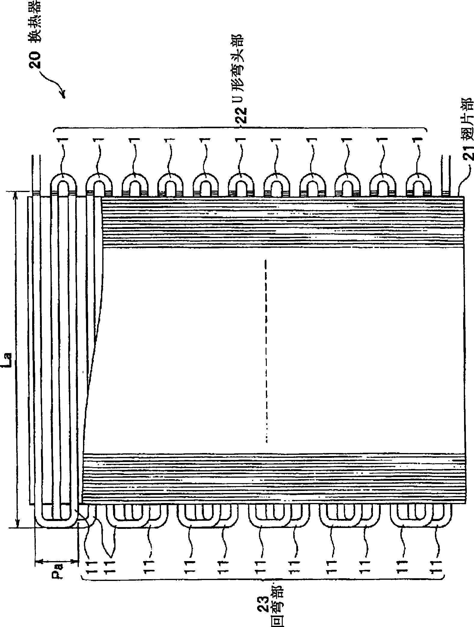
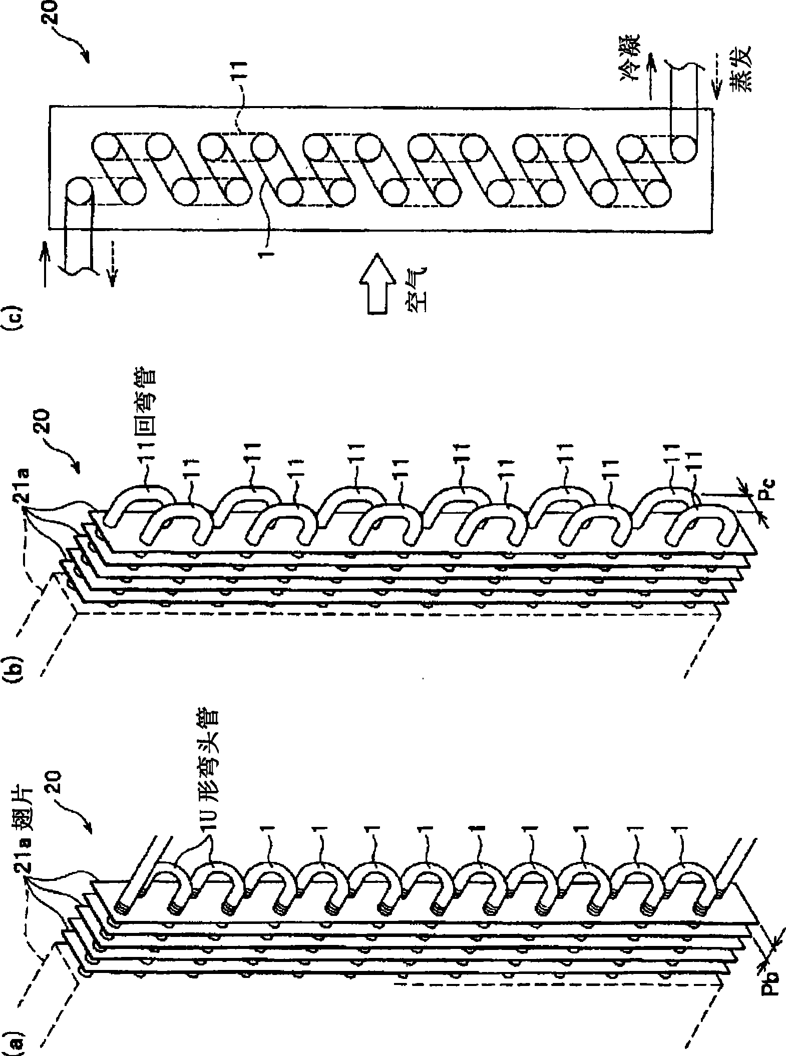
Provided is a fin-and-tube type heat exchanger using a return bend pipe capable of improving the evaporation performance of the heat exchanger still better. This heat exchanger comprises a hair pin unit having a multiplicity of hair pin pipes arranged in parallel, a return bend unit having a multiplicity of such return bend pipes arranged in parallel as are jointed to the individual hair pin pipe end portions of the hair pin portions, and a fin portion having a multiplicity of fins arranged in parallel at a constant spacing on the outer surfaces of the hair pin pipes. The pipe insides are fed with a coolant. The heat exchanger has first grooves formed in the inner faces of the return bend pipes. The groove pitch ratio (P1/P2) between a first groove pitch (P1), as taken in the section normal to the pipe axis, of the first grooves, and a second groove pitch (P2), as taken in the section normal to the pipe axis, of second grooves of a helical shape formed in the pipe inner faces of the hair pin pipes satisfies 0.65 to 2.2. At the same time, the groove sectional area ratio (S1/S2) between a first groove sectional area (S1) per groove, as taken in the section normal to the pipe axis, of the first grooves and a second groove sectional area (S2) per groove, as taken in the section normal to the pipe axis, of the second grooves satisfies 0.3 to 3.6.

Description

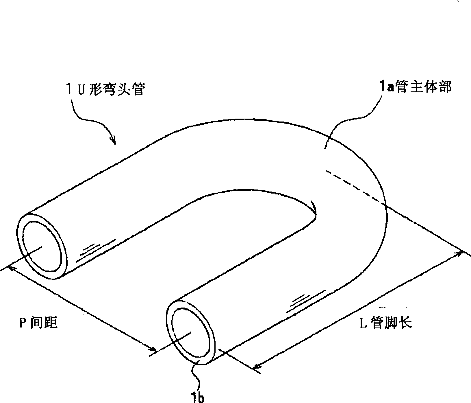
technical field [0001] The invention relates to a finned tube heat exchanger and a U-shaped elbow tube connected with its return bend tube. In heat exchangers such as air-conditioning equipment, especially the finned tube heat exchanger, Freon refrigerant flows inside the tube For refrigerants such as natural refrigerants, a plurality of fins made of aluminum or the like are arranged in parallel on the outside of the tube. Background technique [0002] Currently, Patent Document 1 or Patent Document 2 proposes a finned tube heat exchanger in which a smooth tube with a smooth inner surface is used as a U-shaped elbow tube and a tube with a grooved inner surface is used as a hairpin tube. In addition, in Patent Document 1, the U-shaped elbow pipe is described as a U-shaped elbow pipe, and the return-bent pipe is described as an electric welded steel pipe. In Patent Document 2, the U-shaped elbow pipe is described as a U-shaped elbow, Return bends are recorded as heat pipes. ...

Claims


Application Information

Patent Timeline
IPC IPC(8): F28D1/047F25B39/02F25B1/00F28F1/40
CPCF28F1/40F25B39/02F28F1/42F25B2500/01F28F1/32F28F9/0246F25B2500/09F28D1/0477F28F1/422F28F9/26F25B1/00F28D1/047
Inventor 高桥宏行羽场恒夫石桥明彦
Owner KOBELCO & MATERIALS COPPER TUBE LTD
Why Eureka
Try Eureka