
Induction and electrical arc composite heat source stud welding method

A composite heat source, induction heating power source technology, applied in arc welding equipment, welding equipment, manufacturing tools, etc., can solve the problems of efficiency impact, production efficiency impact, lack of fusion, etc., to improve efficiency, improve welding quality, and facilitate preheating Effect

Active Publication Date: 2009-07-01
NANJING UNIV OF SCI & TECH
View PDF0 Cites 16 Cited by
  • Summary
  • Abstract
  • Description
  • Claims
  • Application Information

AI Technical Summary

Problems solved by technology

[0005] In many specific environments, it is not applicable to use a simple stud welding machine for stud welding. Plate thickness and stud size restrictions
For large thickness plates, such as thickness above 30mm, and stud diameter above 22mm, due to fast heat dissipation, it is easy to cause defects such as lack of fusion and poor forming during simple stud welding; and for some special steel materials such as weapons and armored vehicles The carbon equivalent is high, and the degree of restraint is extremely high. Under stud welding conditions, brittle structures are prone to occur, resulting in welding cold crack defects.
[0006] However, submerged arc pressure welding of rods and plates and electroslag pressure welding also have the disadvantage of poor adaptability. At present, manual operation is required, and the efficiency is affected.
The submerged arc pressure welding of rods and plates takes a long time, and the removal process of unmelted flux and slag shell is added, and the application range is limited. It is only applied to some thick and large flat members, and the equipment is more complicated.
The disadvantage of the electroslag pressure welding method is that the diameter of the workpiece cannot be too small, otherwise a stable molten pool cannot be formed and a stable voltage can be maintained, and the welding time is longer and the grains are coarse.

Method used


Image

  • Induction and electrical arc composite heat source stud welding method
  • Induction and electrical arc composite heat source stud welding method

Examples


Embodiment

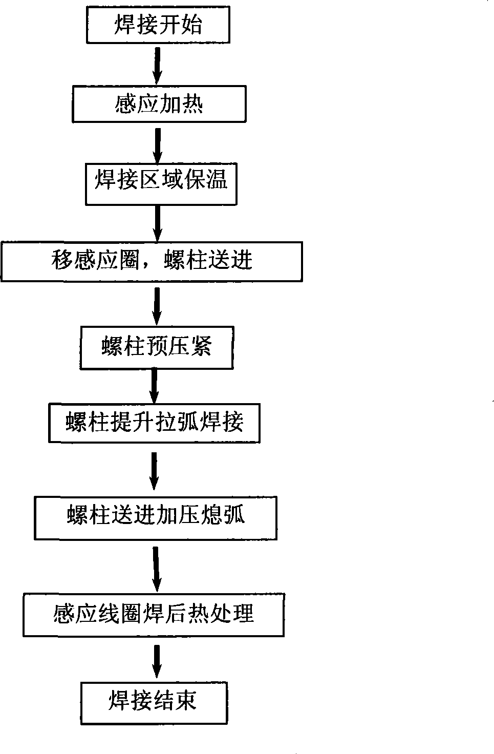
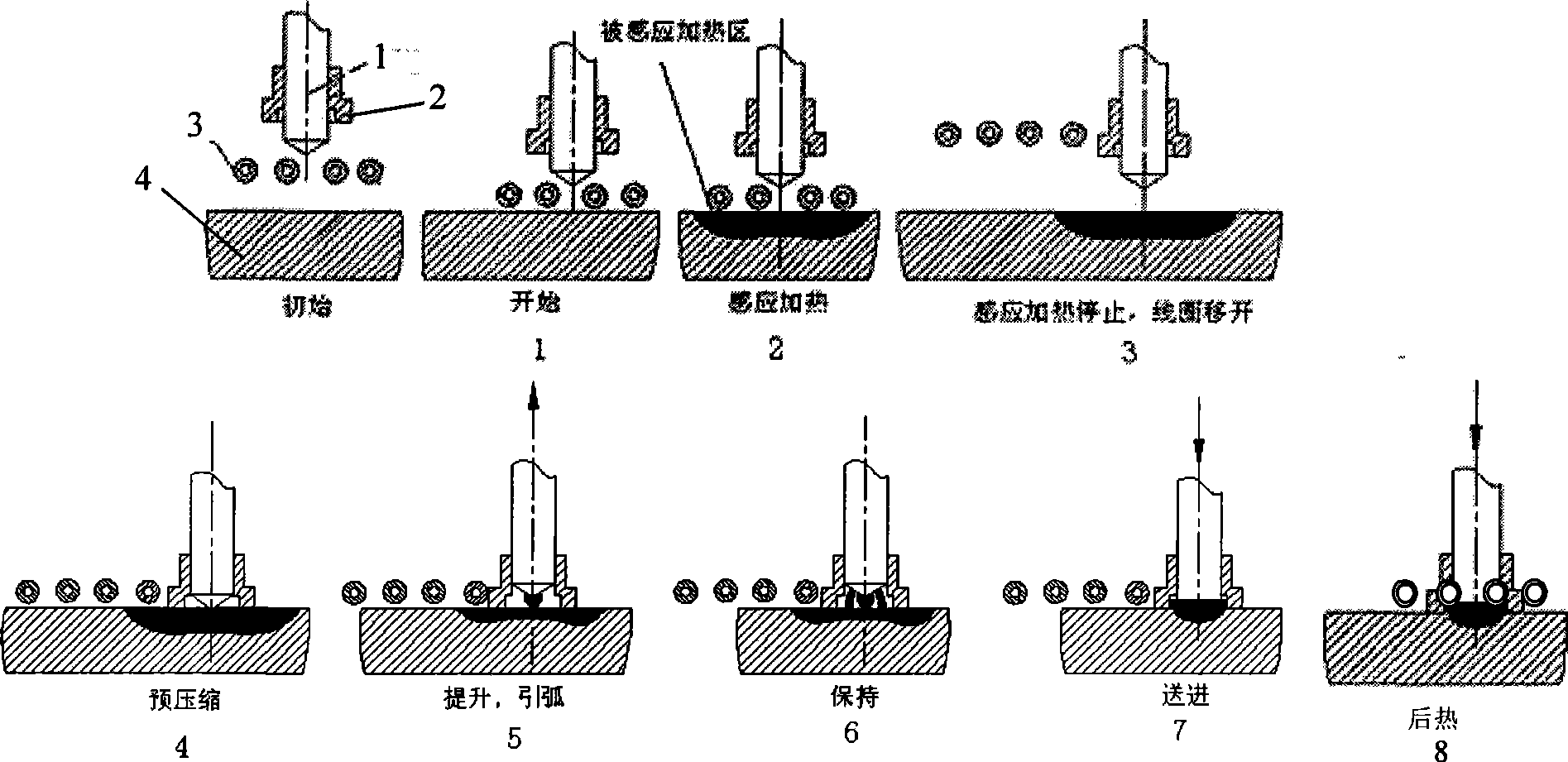
[0015] Example, combined with figure 1 with figure 2 , take stud welding with a diameter of 22mm and a steel plate with a thickness of 20mm as an example. A steel stud with a diameter of 20mm and a length of 60mm is pre-clamped on the stud welding torch, and a ceramic ring 2 is clamped at the front end of the stud. At this time, the stud welding torch and the induction coil 3 should both be in the lifting state. Start the start button of the control system, the induction coil 3 drops to a distance of 3mm, the induction heating power supply heats the welding area of ​​the workpiece 4 through the induction coil 3, the heating time is controlled by the system to 10s, the heating power is 600, and the surface heating temperature of the workpiece 4 is 200 ℃-300℃, after heating, the induction coil 3 is raised, and then the stud welding torch is lowered until the stud and the ceramic ring 2 and the workpiece 4 are kept pre-compressed, the control system sends a welding signal to th...


PUM


Abstract

The invention discloses a method for welding a stud with composite heat resources of induction and electrical arc. The method comprises: an induction heating power supply is adopted to heat a position to be welded, and the induction heating power supply stops working when reaching the preset time and temperature; an electric arc stud welding machine starts working, the end head of the stud carries out striking arc and arcing on the position to be welded, and the stud is sent to a melting pool, cooled and solidified after the melting pool is formed; and an induction coil carries out heat treatment on a joint after welding. The method can weld a board with a thick and large size and realize metallurgical bonding of the stud and a steel board base body. The welding process can realize automatic operation with high efficiency. The joint strength can reach more than 100 percent of the stud strength, and the inner melting rate of the joint is 100 percent. A ceramal sleeve is adopted to protect and obtain the welding joint without inclusions or oxidation. The method can be used for welding a steel board and a steel stud, or an aluminum alloy board and an aluminum alloy stud, or a copper alloy and a copper alloy stud and so on.

Description

technical field [0001] The invention relates to a welding technology on a steel matrix, in particular to a stud welding method of induction and electric arc composite heat source. Background technique [0002] The welding of steel matrix and steel, aluminum, copper studs is widely used in the hull cabin, inside the body of armored vehicles, the inner and outer walls of various pressure vessels, bridges and other fields, and the fields involved in stud welding are becoming more and more extensive. The so-called stud welding refers to the technology of welding the stud to the plate by passing an electric current or forming an arc between the stud and the workpiece to melt the metal. At present, pure capacitor energy storage, arc stud welding technology, manual arc welding, rod plate submerged arc pressure welding, electroslag pressure welding and other technologies are usually used for stud welding. With the rapid development of modern industry, the utilization rate of studs ...

Claims


Application Information

Patent Timeline
Patent Type & Authority Applications(China)
IPC IPC(8): B23K9/20B23K9/235
Inventor 王克鸿张德库顾民乐冯曰海黄俊
Owner NANJING UNIV OF SCI & TECH
Learn More