Electroluminescent device
A technology of electroluminescent devices and light-emitting functional layers, which is applied in the direction of electric solid devices, electrical components, semiconductor devices, etc., can solve the problems of short service life, etc., and achieve the goals of improving service life, improving heat dissipation performance, and improving water and oxygen barrier performance Effect
- Summary
- Abstract
- Description
- Claims
- Application Information
AI Technical Summary
Problems solved by technology
Method used
Image

Examples
Embodiment 1
[0035] This embodiment is used to illustrate the electroluminescent device and its manufacturing method provided by the present invention.
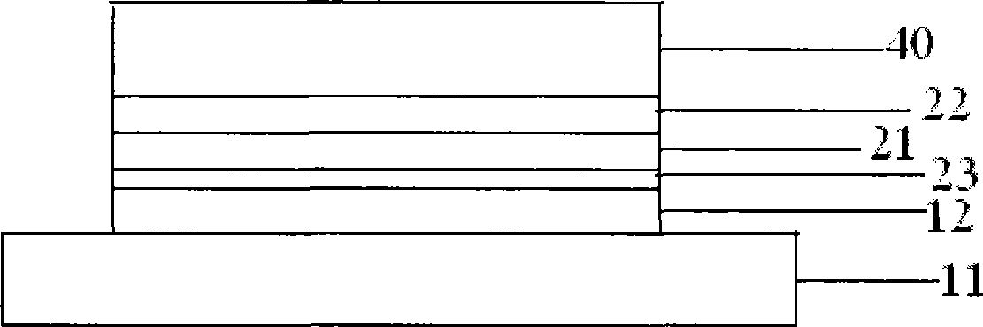
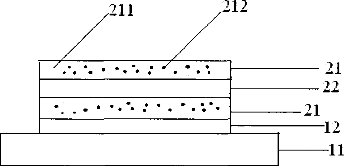
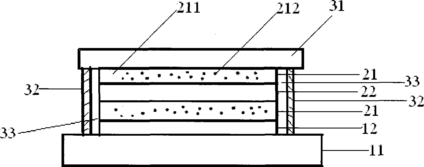
[0036] In a glove box with a water and oxygen content of less than 1ppm and a pressure of 2 atmospheres (wherein the volume ratio of nitrogen and hydrogen is 8:1), 8 parts by weight of CaO with a particle diameter of 50-60 nanometers and 92 parts by weight of CaO A uniform mixture of UV-curable glue (UV STRCTL 352, Loctite Company) was spin-coated onto a luminescent functional layer with a length of 4 cm and a width of 3 cm. The substrate of the luminescent functional layer was an ITO glass substrate, and the organic material layer was 40 mm thick. Nano-N, N'-diphenyl-N, N'-bis(N-phenyl-1-naphthylamine)-biphenylenediamine layer and (8-hydroxyquinoline)-(water A composite layer of a gallium(III) compound layer with a polyphenylaldehyde o-aniline phenol), and a cathode layer of an alloy layer of Mg:Ag (weight ratio 10:1) with a thickness of...
Embodiment 2
[0044] This embodiment is used to illustrate the electroluminescent device and its manufacturing method provided by the present invention.
[0045] In a glove box with a water and oxygen content of less than 1ppm and a pressure of 1.5 atmospheres (in which the volume ratio of nitrogen and hydrogen is 7:1), 10 parts by weight of BaO with a particle diameter of 50-60 nanometers and 90 parts by weight of methyl A homogeneous mixture of methyl acrylate was spin-coated onto an electroluminescent sheet with a length of 4 cm and a width of 3 cm. The substrate of the electroluminescent sheet was an ITO glass substrate, and the organic material layer was 40 nm of N, N'-diphenyl -N,N'-bis(N-phenyl-1-naphthylamine)-biphenylenediamine layer and (8-hydroxyquinoline)-(salicylaldehyde-o-anilinephenol)gallium ( III) A composite layer of layers, the cathode layer is an alloy layer of Mg:Ag (weight ratio 10:1) with a thickness of 200 nanometers. Then UV cured to form a 95nm polymer layer; then...
Embodiment 3
[0047] This embodiment is used to illustrate the electroluminescent device and its manufacturing method provided by the present invention.
[0048] In a glove box with a water and oxygen content of less than 1ppm and a pressure of 1.8 atmospheres (in which the volume ratio of nitrogen and hydrogen is 10:1), 9 parts by weight of MgO with a particle diameter of 50-55 nanometers and 91 parts by weight of methyl A homogeneous mixture of ethyl acrylate was spin-coated onto an electroluminescent sheet with a length of 4 cm and a width of 3 cm. The substrate of the electroluminescent sheet was an ITO glass substrate, and the organic material layer was a 40-nm-thick N,N'-di Phenyl-N,N'-bis(N-phenyl-1-naphthylamine)-biphenylenediamine layer and (8-hydroxyquinoline)-(salicylaldehyde-o-anilinephenol) compound with a thickness of 40 nm The composite layer of the gallium (III) layer, the cathode layer is an alloy layer of Mg:Ag (weight ratio 10:1) with a thickness of 200 nm. Then UV cured...
PUM
| Property | Measurement | Unit |
|---|---|---|
| Thickness | aaaaa | aaaaa |
| Thickness | aaaaa | aaaaa |
Abstract
Description
Claims
Application Information
 - R&D
- Intellectual Property
- Life Sciences
- Materials
- Tech Scout
- Unparalleled Data Quality
- Higher Quality Content
- 60% Fewer Hallucinations
Browse by: Latest US Patents, China's latest patents, Technical Efficacy Thesaurus, Application Domain, Technology Topic, Popular Technical Reports.
© 2025 PatSnap. All rights reserved.Legal|Privacy policy|Modern Slavery Act Transparency Statement|Sitemap|About US| Contact US: help@patsnap.com