LLC resonant transformation device

A technology of resonant converter and resonant circuit, which is applied to instruments, conversion equipment with intermediate conversion to AC, DC power input conversion to DC power output, etc., which can solve the problems of unreliable operation, output voltage backfeeding, and limited efficiency improvement And other problems, to achieve the effect of preventing straight-through or output voltage backfeeding, improving efficiency, and avoiding short-term backfeeding

Inactive Publication Date: 2009-07-01
SHENZHEN MINDRAY BIO MEDICAL ELECTRONICS CO LTD
View PDF0 Cites 36 Cited by
  • Summary
  • Abstract
  • Description
  • Claims
  • Application Information

AI Technical Summary

Problems solved by technology

[0022] (1) The drive signals Vg_Q1 and Vg_Q2 of the secondary-side synchronous rectifier switch tubes are synchronized with the drive signals Vg_S1 and Vg_S2 of the primary-side switch tubes, so that during the period t0~t1 and t2~t3, the body of the secondary side synchronous rectifier switch tubes Q1 and Q2 The diode conducts and the loss increases
[0023] (2) Taking signals from the p

Method used


Image

  • LLC resonant transformation device
  • LLC resonant transformation device
  • LLC resonant transformation device

Examples


Embodiment 1

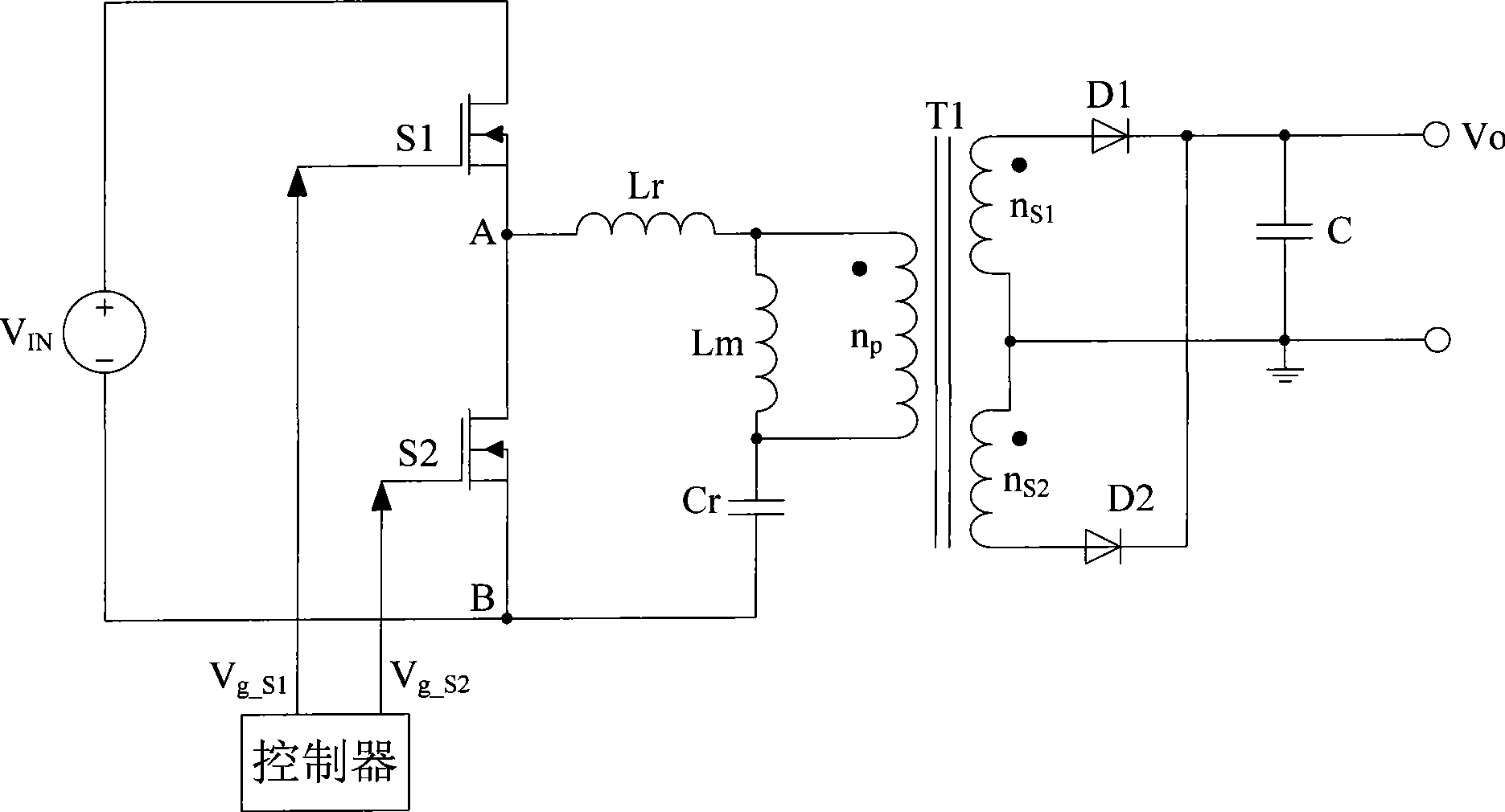
[0045] Such as Figure 8 As shown, what this example proposes is a LLC resonant half-bridge converter with synchronous rectification.

[0046] The input of the LLC resonant half-bridge converter is a DC voltage V IN 101.

[0047] The primary-side bridge circuit 102 adopts a half-bridge circuit, including power switch tubes S1 and S2, for driving the subsequent LLC resonant circuit.

[0048] The LLC resonant circuit 103 includes a series resonant capacitor Cr, a series resonant inductance Lr and a magnetizing inductance Lm of the transformer T1, wherein the series resonant inductance Lr can be an independent inductance or the leakage inductance of the transformer T1.

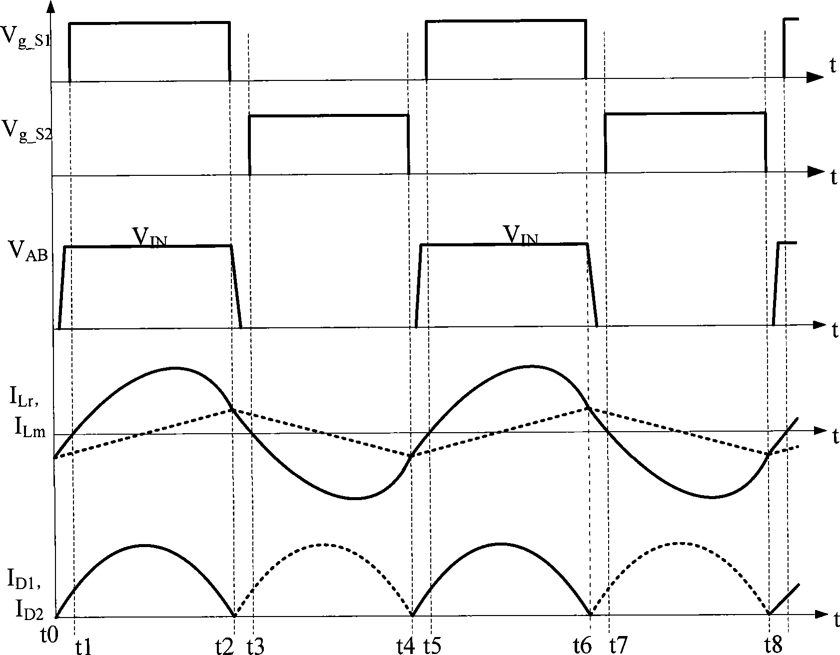
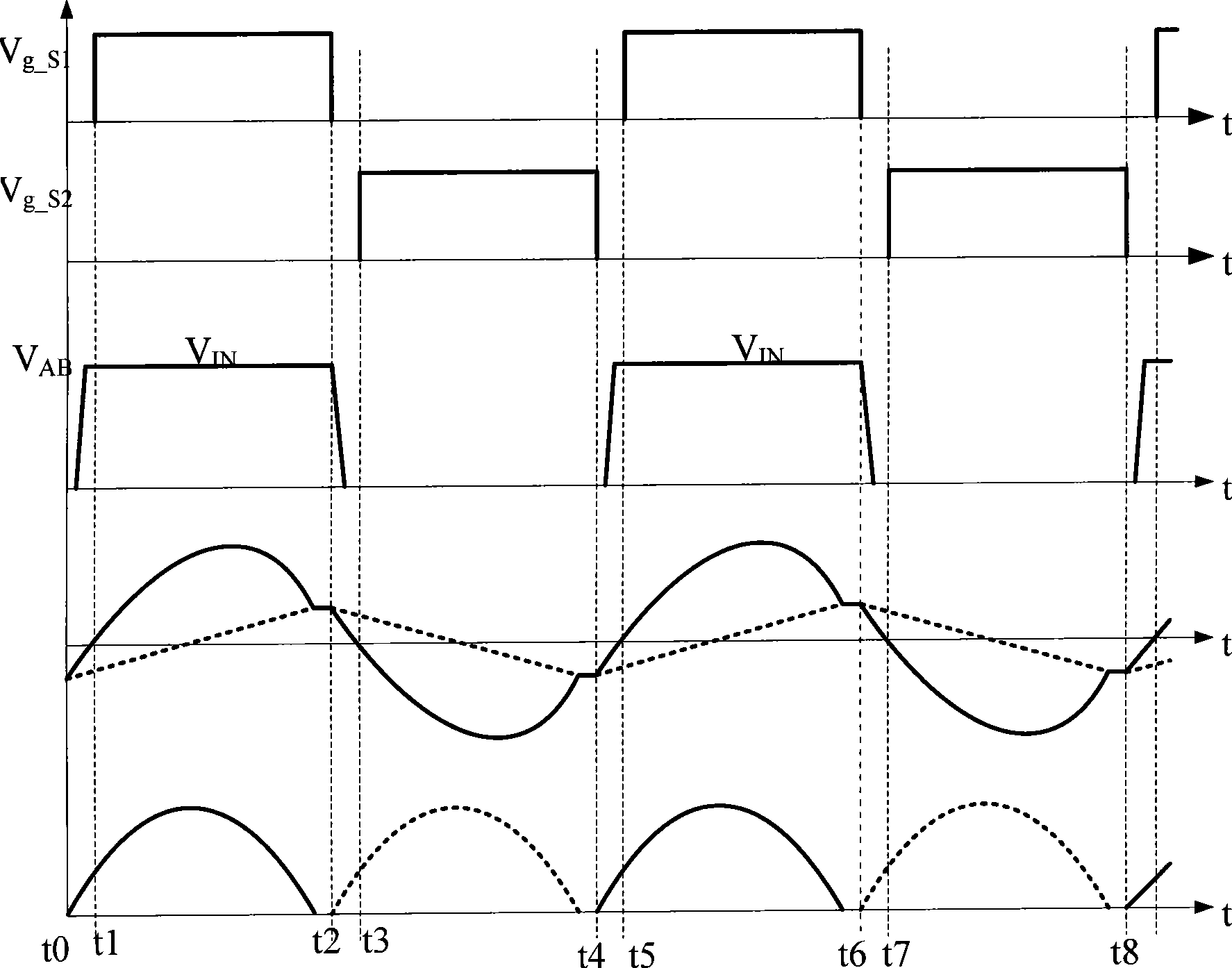
[0049] The primary-side controller 104 is used to generate a driving signal to control the power switch tubes S1 and S2 of the half-bridge circuit to be turned on or off. The controller makes the power switch tubes S1 and S2 conduct alternately, and works at a constant duty cycle (the duty cycle is slightly le...

Embodiment 2

[0065] Please refer to Figure 10 Shown is the functional block diagram of the LLC resonant full-bridge converter with synchronous rectification in this example. On the basis of the LLC resonant full-bridge converter without synchronous rectification in the prior art, a secondary side controller is added to control the secondary side synchronous rectification switching tubes Q1 and Q2. The secondary-side controller controls the secondary-side synchronous rectification switch tubes Q1 and Q2 through the zero-crossing detection of the secondary-side winding current, so that the secondary-side synchronous rectification switch tubes Q1 and Q2 are turned on when the current is greater than zero, and turned off at other times. broken. Through accurate current detection, the loss of the secondary side rectifier circuit of the LLC resonant full bridge converter is reduced to the minimum, and at the same time, it can effectively prevent the two secondary side synchronous rectification...


PUM


Abstract

The invention discloses an LLC resonant converter comprising a primary side bridge circuit, an LLC resonant network, a primary side controller, a power supply conversion circuit, a synchronous rectifier circuit, a secondary side controller and a current detection circuit. The current detection circuit is connected in a loop of the synchronous rectifier circuit in series, a detection signal output terminal thereof is connected with an input terminal of the secondary side controller, and a control signal output terminal of the secondary side controller is connected with the synchronous rectifier circuit; and the secondary side controller controls the switching-on/off of the synchronous rectifier circuit through the zero-crossing detection of the output current of the power supply conversion circuit, thereby enabling the synchronous rectifier circuit to be switched on when the current is greater than zero and be switched off in the remaining time. The LLC resonant converter can avoid the coupling delay when a switch tube of the primary side bridge circuit and the switch tube of the synchronous rectifier circuit are conducted, thereby improving the efficiency and the reliability of the converter.

Description

【Technical field】 [0001] The invention relates to a switching power supply circuit, in particular to a resonant converter therein. 【Background technique】 [0002] With the development of switching power supply technology, high power density and high efficiency have become the development trend. In this case, soft switching technology has been widely developed and applied. The circuit topologies used in soft switching technology mainly include resonant soft switching topology and PWM soft switching topology. In recent years, with the development of semiconductor device manufacturing technology, the on-resistance, parasitic capacitance and reverse recovery time of the switch tube have been reduced, creating conditions for the realization of the resonant converter. The LLC resonant half-bridge converter is one of them. It keeps the conduction duty cycle of the upper and lower bridge arm switches unchanged, and adjusts the output voltage by adjusting the switching frequency to ...

Claims


Application Information

Patent Timeline
IPC IPC(8): H02M3/28H02M3/335
CPCY02B70/1475Y02B70/1433
Inventor 周小军李伟练荣辉
Owner SHENZHEN MINDRAY BIO MEDICAL ELECTRONICS CO LTD
Why Eureka
Try Eureka