
Alignment system and alignment method for photolithography equipment

An alignment system and lithography equipment technology, applied in the field of alignment systems, can solve the problems of low alignment scanning signal strength and signal-to-noise ratio, large occupied space, phase mismatch, etc., so as to improve energy utilization and improve alignment. Quasi-accuracy, signal-to-noise ratio and the effect of increased intensity

Active Publication Date: 2009-08-19
SHANGHAI MICRO ELECTRONICS EQUIP (GRP) CO LTD +1
View PDF2 Cites 5 Cited by
  • Summary
  • Abstract
  • Description
  • Claims
  • Application Information

AI Technical Summary

Problems solved by technology

However, in the alignment system, the alignment marks are lined up on the silicon wafer and the reference board, and they are all alignment marks in one direction. The corresponding reference marks are divided into eight branches, which will bring many shortcomings: alignment marks The space occupied by the corresponding reference mark is relatively large, which makes the energy utilization rate of the light source low, and factors such as photolithography process and silicon wafer deformation have a relatively large impact on the alignment accuracy; when the coherent image of the diffracted beam of the alignment mark is scanned with the reference mark , the obtained alignment scan signal intensity has an obvious inflection point, which is not conducive to the later AGC gain and other related signal processing; when the middle branch of the reference mark scans in one direction, the two branches of the reference mark scan an alignment at the same time. The coherent image of the beam diffracted by the quasi-mark grating, no light can enter the detection fiber and photodetector behind the reference mark in the blank part of the two branches, which makes the intensity and signal-to-noise ratio of the alignment scanning signal very low, and will cause two The coherent image of a reference mark branch relative to the alignment mark diffracted beam has a phase mismatch problem, which is not conducive to the alignment of the alignment mark and signal processing; two small period reference marks in the same direction are in the case of sufficient alignment signal energy. The lower requirements should be as small as possible, but at the same time, the diameter of the detection fiber behind the reference mark becomes smaller and the space is difficult to couple with the reference mark

Method used


Image

  • Alignment system and alignment method for photolithography equipment
  • Alignment system and alignment method for photolithography equipment
  • Alignment system and alignment method for photolithography equipment

Examples


Embodiment Construction

[0036] The alignment system and alignment method for lithography equipment proposed by the present invention will be further described in detail below with reference to the accompanying drawings and specific embodiments.

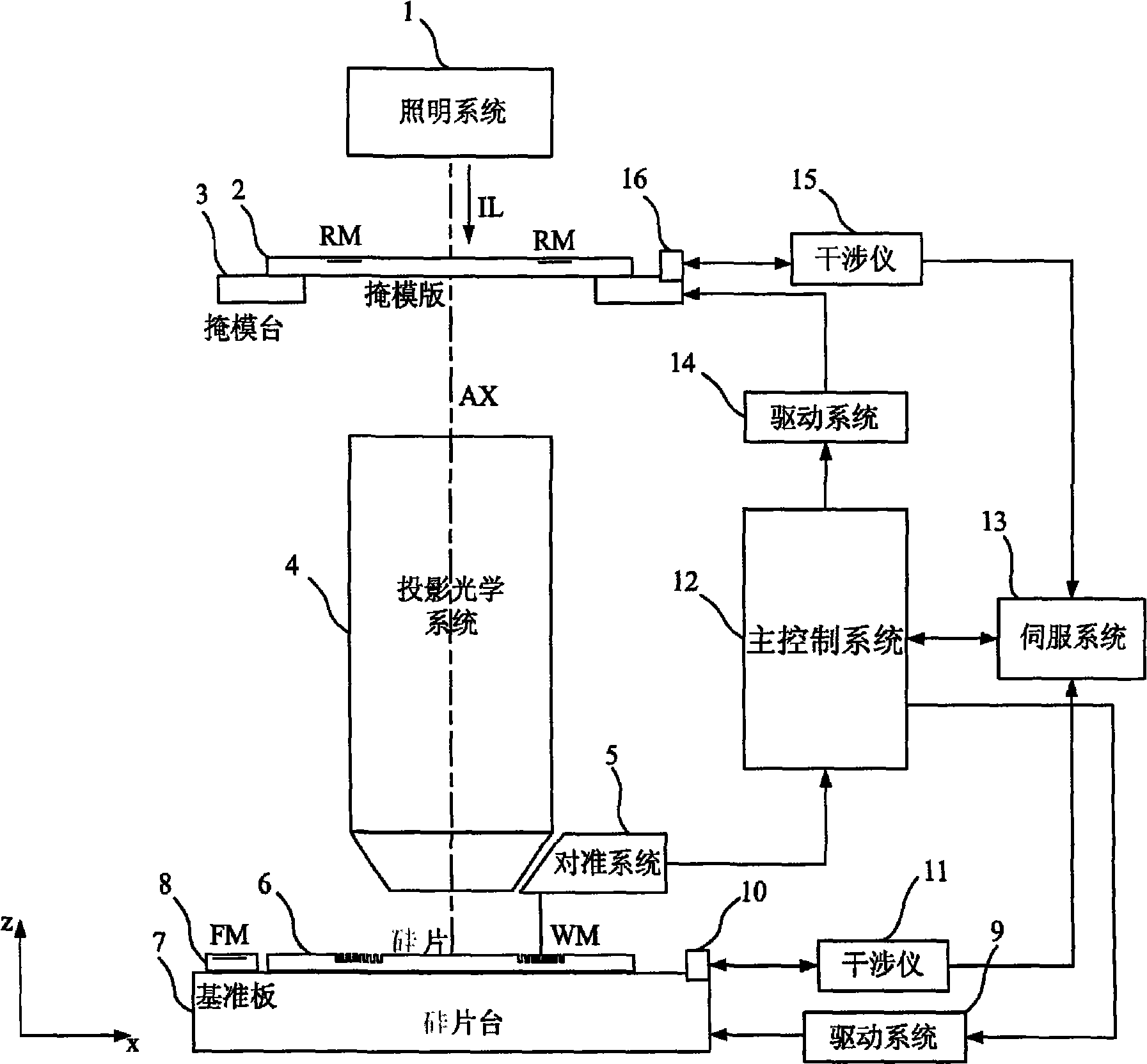
[0037] Please refer to figure 1 , which is a schematic structural diagram of the overall layout and working principle between the alignment system of the lithography equipment provided by an embodiment of the present invention and the lithography equipment. The lithography apparatus comprises: an illumination system 1 for providing an exposure light beam; a mask support and a mask table 3 for supporting a reticle 2 on which a mask pattern and an alignment mark having a periodic structure are provided RM; a projection optical system 4 for projecting the mask pattern on the reticle 2 onto the wafer 6; a wafer holder for supporting the wafer 6 and a wafer stage 7 with fiducial marks engraved on the wafer stage 7 Reference plate 8 for FM, alignment marks with p...


PUM


Abstract

The invention provides an alignment system which is used for lithography equipment, and an alignment method thereof; the middle branch of a reference mark adopted by the alignment system is a sharing reference mark which consists of bar-shaped amplitude gratings on different directions and thus a new form of reference mark is formed; the position scanning of two directions can be realized; compared with the prior art, the signal-noise ratio and strength of the alignment signals is led to be improved; the energy using efficiency is improved; the obtained alignment scanning signals do not show obvious inflection points, thus being beneficial to the processing of the later signal detection and AGG gain and other parts; and the alignment accuracy is improved.

Description

technical field [0001] The present invention relates to photolithography equipment, in particular to an alignment system and an alignment method for photolithography equipment. Background technique [0002] The lithography equipment in the prior art is mainly used in the manufacture of integrated circuits (ICs) or other micro devices. Through photolithography equipment, multi-layer masks with different mask patterns are sequentially exposed and imaged on a silicon wafer coated with photoresist under precise alignment. The current lithography equipment is roughly divided into two categories, one is stepping lithography equipment, the mask pattern is exposed and imaged on one exposure area of ​​the silicon wafer, and then the silicon wafer moves relative to the mask to move the next exposure area Go to the mask pattern and under the projection objective lens, again expose the mask pattern on another exposed area of ​​the silicon wafer, and repeat this process until all expose...

Claims


Application Information

Patent Timeline
IPC IPC(8): G03F7/20G03F9/00
Inventor 杜聚有徐荣伟王诗华
Owner SHANGHAI MICRO ELECTRONICS EQUIP (GRP) CO LTD
Features
  • Generate Ideas
  • Intellectual Property
  • Life Sciences
  • Materials
  • Tech Scout
  • Unparalleled Data Quality
  • Higher Quality Content
  • 60% Fewer Hallucinations
Learn More