
AC arc welding system and method thereof

A welding system and AC arc technology, applied in arc welding equipment, welding equipment, manufacturing tools, etc., can solve the problems of inability to effectively reduce energy, limited reduction of base metal heat input, and difficult to popularize welding wire, and achieve easy arc length. Adjustment, easy exchange of reversing, precise and controllable effect of wire feeding process

Inactive Publication Date: 2009-09-09
BEIJING UNIV OF TECH
View PDF0 Cites 26 Cited by
  • Summary
  • Abstract
  • Description
  • Claims
  • Application Information

AI Technical Summary

Problems solved by technology

However, no matter what kind of process is used, there are big shortcomings: the CMT method still uses DC reverse connection mode to work, although the energy is reduced in the short circuit stage, but because the short circuit energy itself is very small, the reduction of the heat input of the base metal is limited. Only slightly lower than the traditional surface tension transition method (STT); the cold arc welding method uses a special welding wire, which is not easy to promote, and also uses the DC reverse connection method, which cannot effectively reduce energy
In the early stage of Beijing University of Technology, the over-push and wire-drawing method was used to realize low-energy welding, and different methods were used to achieve similar functions to CMT, but the power supply also adopted the form of DC reverse connection, and a large part of the heat during the arcing period was used to heat the base metal. Therefore, there is still a lot of room for energy reduction

Method used

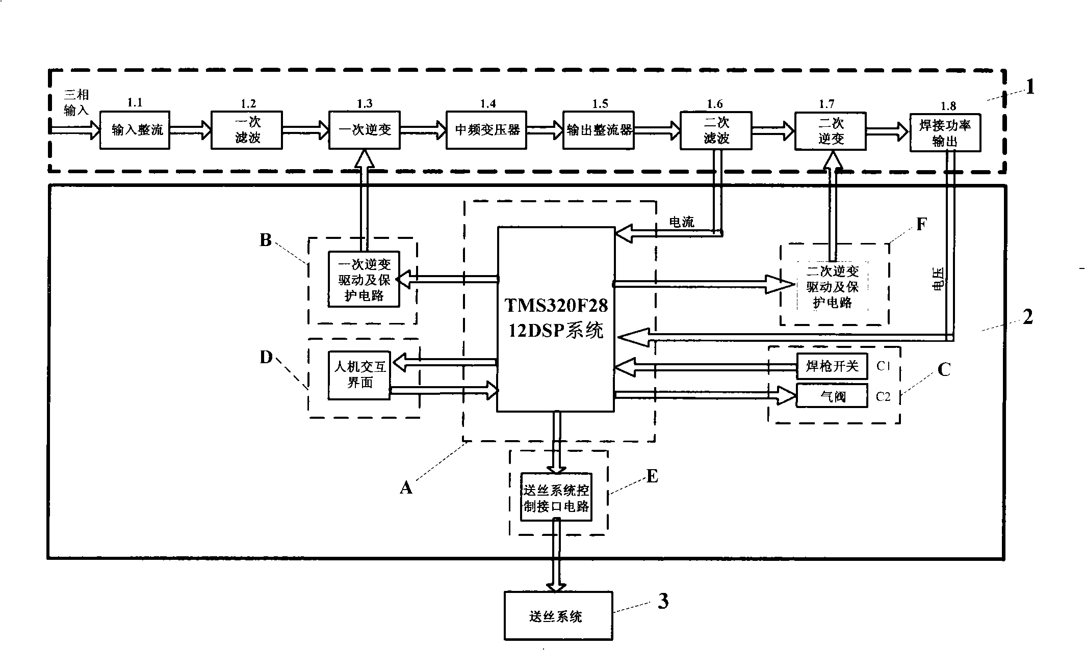

Image

  • AC arc welding system and method thereof
  • AC arc welding system and method thereof
  • AC arc welding system and method thereof

Examples


Embodiment Construction

[0023] The present embodiment will now be described with reference to the drawings. (embodiment carries out the welding of butt weld seam at the 3A21 aluminum alloy plate of 1mm thickness)

[0024] A specific example of the present invention, the structure of the low-energy input arc welding system is as follows: figure 1 As shown, it generally includes two parts: welding system and wire feeding system.

[0025] The welding system includes a main circuit part 1 and a control circuit part 2 with TMS320F2812DSP as the core. The input voltage of the main circuit is three-phase 380V; the input rectification 1.1 is rectified by Fuji rectifier bridge, the model is FUJ 6RI100G-160; the primary inverter circuit 1.3 adopts the half-bridge inverter structure, which is composed of two IGBTs whose model is BSM150GB120DN2; the intermediate frequency transformer 1.4 Ultramicrocrystalline magnetic core is used, and the transformation ratio is 15:2; the secondary filter 1.6 adopts magnetic ...

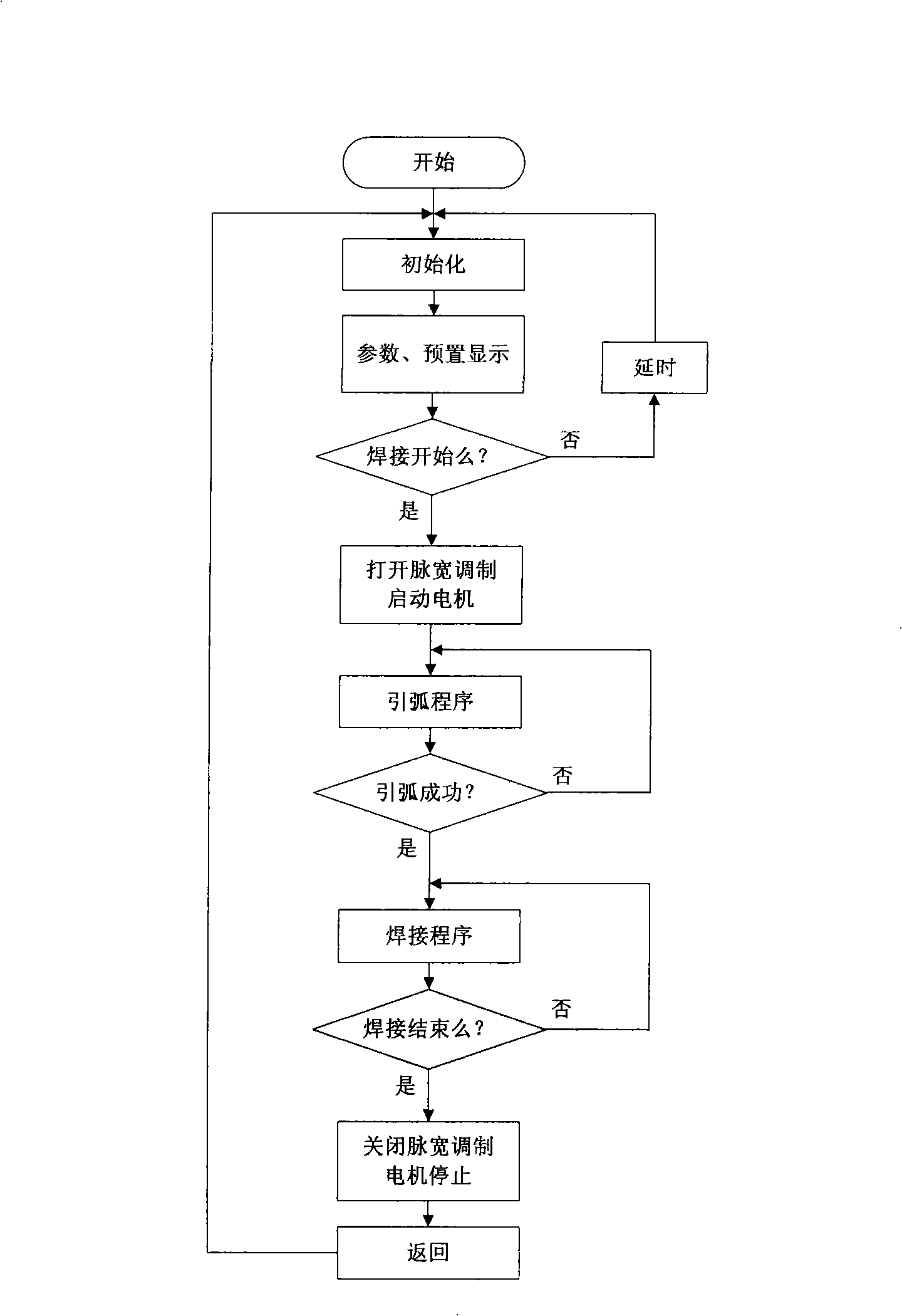

PUM


Abstract

The invention relates to an AC arc welding system and a method thereof, belonging to the welding equipment and automation field. The system adopts a wire feeding mode of wire pushing and drawing. A power supply adopts an AC output mode. The system concretely comprises a welding power system and a wire feeding system. The welding power system mainly comprises a main circuit part (1) for providing power output for welding and a control circuit part (2) for controlling the output power of the main circuit. The wire feeding system adopts an AC servo motor as a wire feeding motor and controls an interface circuit (E) by the wire feeding system to receive signals sent by a DSP system (A). The wire feeding motor reciprocates to realize the wire pushing and drawing. Simultaneously, a welding power judges that the welding is in the short circuit / arcing state according to the feedback voltage to change the output polarity of the power. The droplet short circuiting transfer is finished under the function of welding pumpback tension. A small short circuit current is adopted. In addition, the straight polarity direct current is adopted at the arcing initial stage. More arc energy can be distributed to welding wires, and the heat input of base metal is lowered greatly.

Description

technical field [0001] The invention relates to an AC input arc welding system and method, belonging to the field of welding equipment and automation. Background technique [0002] Low energy input arc welding is a welding method for thin plates, which is still in its infancy. At present, there are two main welding methods, one is called cold metal transition welding (CMT), and the other is called cold arc welding. Both welding methods use the droplet transfer method of short-circuit transfer, but their process characteristics are quite different. For the first form, the push-pull wire feeding method is adopted, and a specially designed wire feeding system is used. The wire feeder completes the forward and reverse actions at a high frequency, and the short circuit signal is detected during the welding process and fed back to the wire feeder. The wire feeder responds by withdrawing the welding wire, thereby separating the welding wire from the droplet and reducing the energy...

Claims

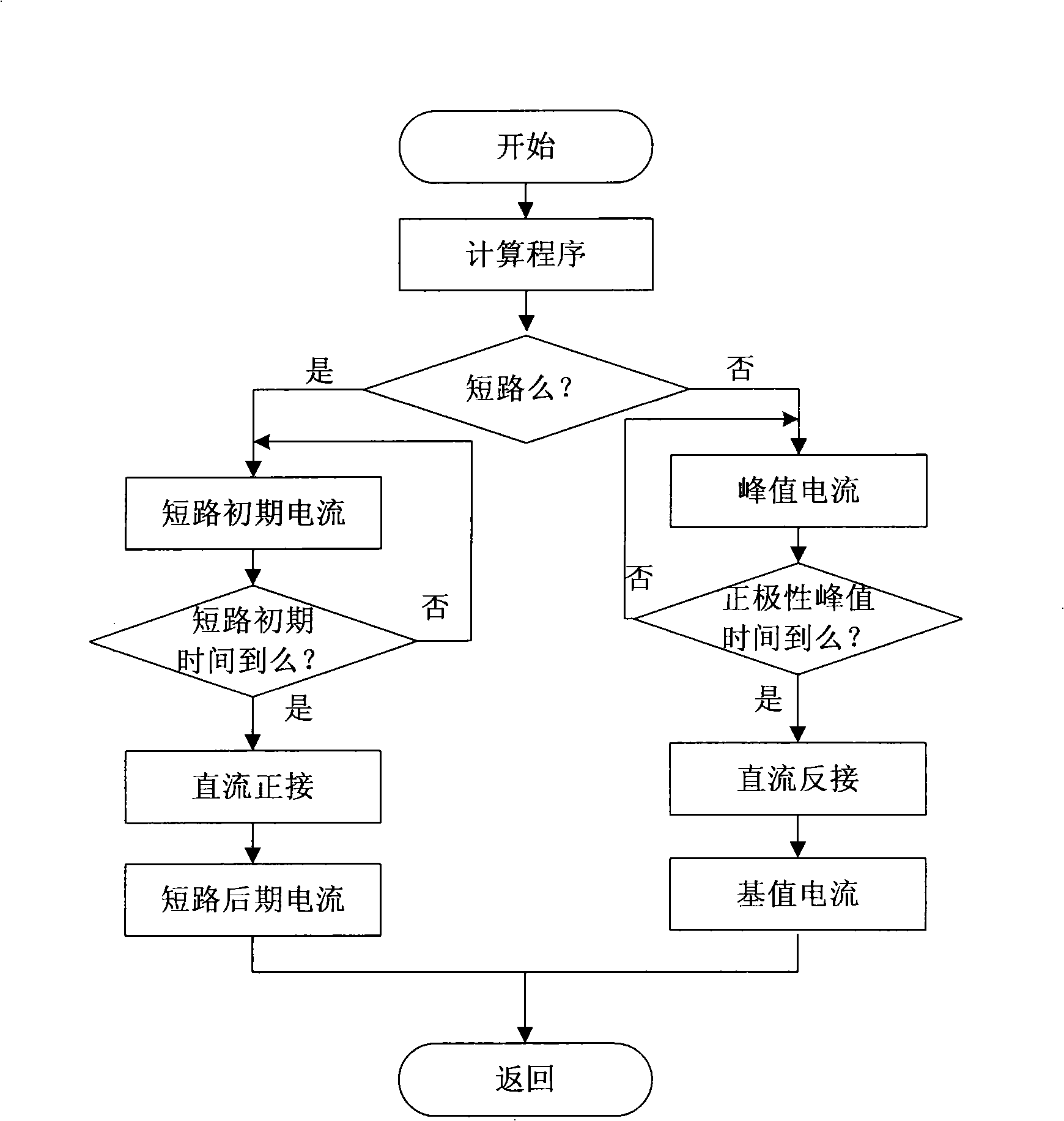

Application Information

Patent Timeline
IPC IPC(8): B23K9/00B23K9/10B23K9/133B23K9/095
Inventor 卢振洋黄鹏飞高文宁
Owner BEIJING UNIV OF TECH
Learn More