Method for preparing surface enhanced Raman scattering optical fiber probe

A surface-enhanced Raman and fiber optic probe technology, which is applied in Raman scattering, material excitation analysis, etc., can solve the problems of high operational difficulty, poisonous and harmful corrosive liquid, and difficulty in accurately controlling the corrosion morphology of the end face of the optical fiber. Simple, low-cost effect

Inactive Publication Date: 2009-09-23
TSINGHUA UNIV
View PDF0 Cites 28 Cited by
  • Summary
  • Abstract
  • Description
  • Claims
  • Application Information

AI Technical Summary

Problems solved by technology

The preparation process of this method is simple, but the modification of the optical fiber end face by the corrosive liquid has certain randomness, it is difficu

Method used


Image

  • Method for preparing surface enhanced Raman scattering optical fiber probe
  • Method for preparing surface enhanced Raman scattering optical fiber probe
  • Method for preparing surface enhanced Raman scattering optical fiber probe

Examples


Embodiment 1

[0027] (1) Silver nitrate solution (1 mM) and sodium citrate solution (1 mM) were mixed, and 100 μL of the mixed solution was taken as reaction solution 4.

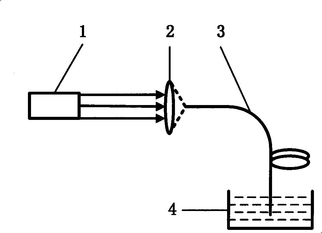
[0028] (2) Refer to figure 1 , the laser light source 1 is a helium-neon laser, and the central wavelength of the output laser is 632.8nm. Optical fiber 3 is a standard single-mode optical fiber with a cladding diameter of 125 μm and a core diameter of 9 μm. Both ends of the optical fiber are cut to be perpendicular to the axis of the optical fiber. The laser light output from the laser light source 1 is coupled into the near end of the optical fiber 3 through the converging lens 2, and the laser light propagates in the optical fiber according to the fundamental mode, and the output power from the far end of the optical fiber 3 is 4.25mW.

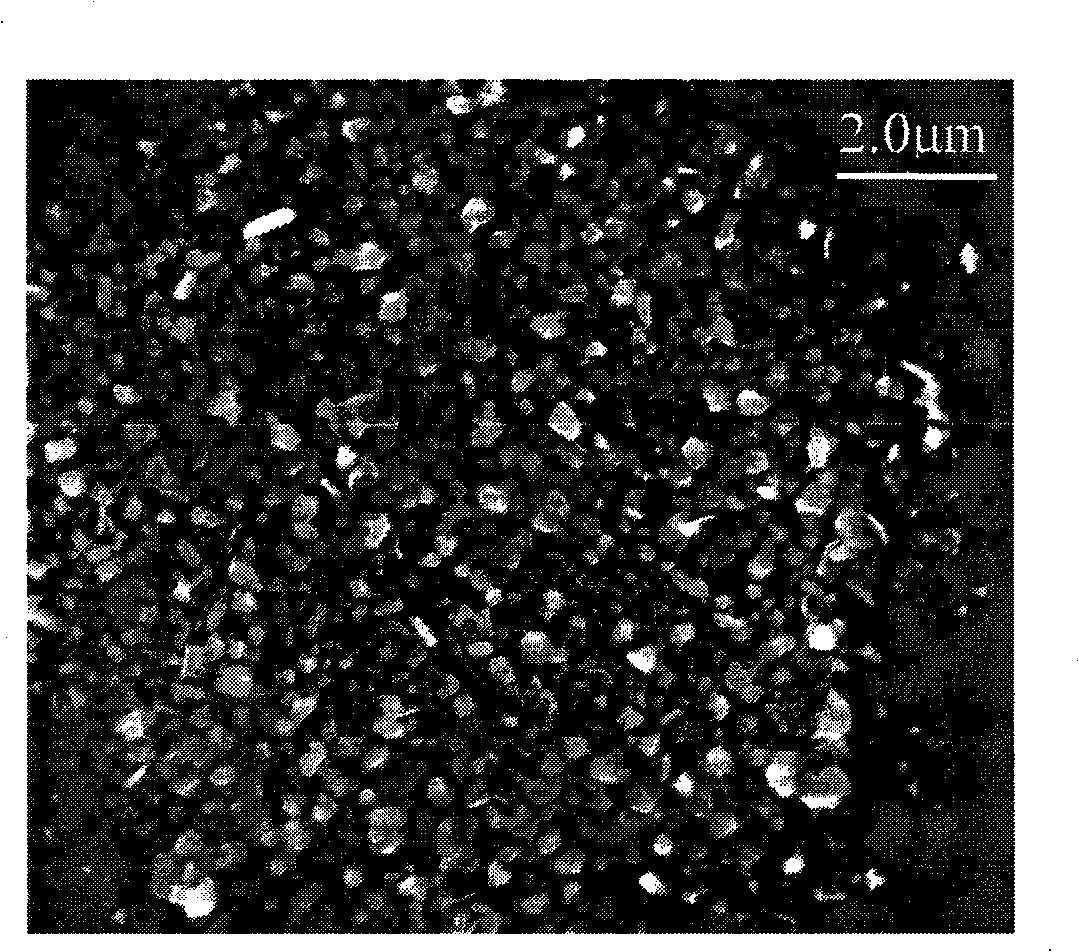
[0029] (3) The distal end of the optical fiber 3 is immersed in the reaction solution 4 . After 3 minutes of laser irradiation, the silver ions in the reaction solution were reduced ...

Embodiment 2

[0032] Example 2: Silver nitrate solution (0.1 mM) and sodium citrate solution (1 mM) were mixed, the output power of the laser at the far end of the optical fiber 3 was 6.00 mW, and the rest of the reaction conditions were referred to in Example 1. After 10 minutes of laser irradiation, silver nanoparticle deposition was formed on the core region of the far end of the fiber, thereby obtaining a surface-enhanced Raman scattering fiber probe.

Embodiment 3

[0033] Example 3: Silver nitrate solution (2mM) and sodium citrate solution (1mM) were mixed, the output power of the laser at the far end of the optical fiber 3 was 6.00mW, and the rest of the reaction conditions were referred to in Example 1. After irradiating the laser for 1 min, silver nanoparticle deposition was formed on the core region of the far end face of the fiber, thereby obtaining a surface-enhanced Raman scattering fiber probe.


PUM


Abstract

The invention relates to a method for preparing a surface enhanced Raman scattering (SERS) optical fiber probe, which comprises the steps as follows: the laser-transmitting characteristic of optical fiber is utilized to form an optical field with graded distribution on the fiber end surface; the remote end of the optical fiber is immersed in a reaction solution containing a reducing agent and soluble metal salt; under laser radiation, metal cations in the reaction solution are reduced into metal nano particles, and the particles are adhered on the core field of the fiber end surface under the gradient force action of the optical field to form a deposition pattern with distribution being the same as the laser mode field of the remote end surface of the optical fiber and then taken as a substrate needed by surface enhanced Raman detection, thus obtaining the optical fiber probe applied to SERS detection. The method utilizes the laser power, action time and optical spot profile of laser on the fiber end surface to respectively control the size of the metal nano particles and the deposition shape thereof at the fiber end surface, thus providing a new method for controlling the properties of the surface enhanced Raman probe.

Description

technical field [0001] The invention relates to a method for preparing an optical fiber probe used in surface-enhanced Raman scattering detection, in particular to a method for preparing an optical fiber probe by laser induction, which is applied to the fields of optical fiber sensing, near-field enhanced Raman detection, etc. . Background technique [0002] Surface-Enhanced Raman Scattering (SERS) detection can provide spectral information about the fine structure of molecules, and is a molecular recognition method to achieve high-sensitivity, label-free detection. The use of fiber optic probes for SERS detection enables detection to be performed in remote, micron-sized environments. The formation of metal micro-nano structures on the end faces of fiber optic probes is of great help to improve the performance of the probes. [0003] At present, there are several methods for forming metal micro-nano structures at the end of optical fibers to obtain surface-enhanced Raman o...

Claims


Application Information

Patent Timeline
IPC IPC(8): G01N21/65
Inventor 杨昌喜黎铭珊
Owner TSINGHUA UNIV
Why Eureka
Try Eureka