Method and apparatus of blast furnace slag quench and heat recovery

A waste heat recovery and blast furnace slag technology, which is applied in the direction of recycling technology and process efficiency improvement, can solve the problems of increasing the flow rate of cooling medium, low quality of recovered heat, contradiction between cooling speed and heat recovery effect, etc., and achieve rapid cooling , Simple structure, easy installation

Active Publication Date: 2009-10-07
TSINGHUA UNIV
View PDF0 Cites 20 Cited by
  • Summary
  • Abstract
  • Description
  • Claims
  • Application Information

AI Technical Summary

Problems solved by technology

To obtain a large cooling in a short period of time, the flow rate of the cooling medium must be increased, which wi

Method used


Image

  • Method and apparatus of blast furnace slag quench and heat recovery
  • Method and apparatus of blast furnace slag quench and heat recovery

Examples


Embodiment 1

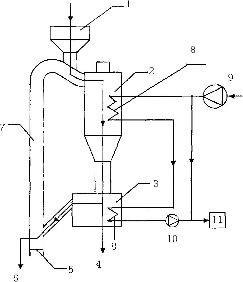
[0016] A device for rapid cooling and waste heat recovery of blast furnace slag, figure 1 For the working system and the blast furnace slag and cooling water circulation loop, the circulating fluidized bed is used to quench the blast furnace slag and recover the waste heat. The pipe connecting the riser to the separator is inclined to the direction of the separator 2 at an angle of 60° to the separator. The inclination angle is used to avoid Blast furnace slag accumulates at the slag inlet, the blast furnace slag inlet 1 is installed on the pipe connecting the riser 7 to the separator, the storage tank 3 is set under the separator 2, the storage tank 3 is set with the coarse slag discharge port 4, and the storage tank 3 Connected to the riser pipe 7, an air distribution plate 5 and a fine slag discharge port 6 are arranged at the lower end of the riser pipe 7, and a water wall 8 is arranged around the separator 2 and the storage tank 3.

[0017] The cooling water in the water wal...

Embodiment 2

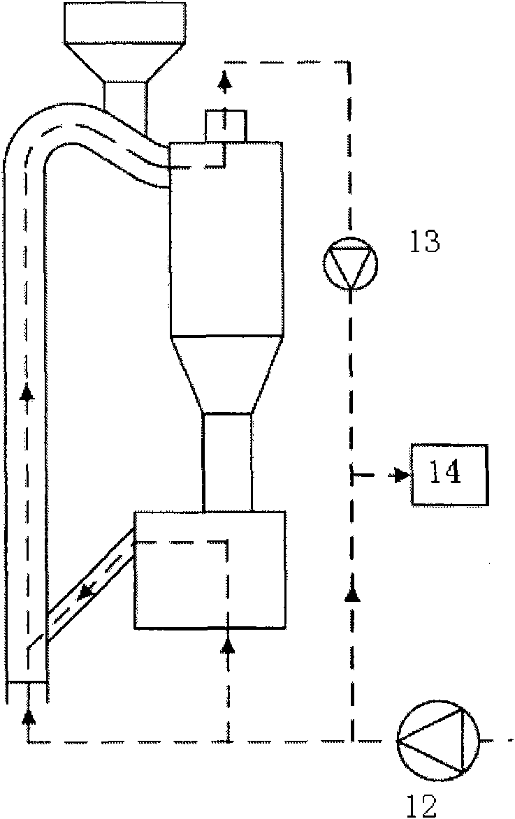
[0020] The device of Example 1 is used to rapidly cool blast furnace slag and recover waste heat. The method steps are as follows. After the blast furnace slag is discharged from the blast furnace, it enters the circulating fluidized bed through the blast furnace slag inlet 1, and the fan 12 is provided by the air distribution plate of the riser 7 The fluidizing air blows the blast furnace slag into the separator 2 to achieve gas-solid separation and then enters the storage tank 3. The water-cooled wall 8 arranged outside the separator 2 works together with the fluidizing air to quickly cool the blast furnace slag After granulation, the granulated slag enters the storage tank 3. The fluidizing air provided by the fan 12 passing under the storage tank 3 makes the blast furnace slag form a bubbling bed in the storage tank 3. The water-cooled wall 8 arranged outside the storage tank 3 further cools the blast furnace slag. On the other hand, the fluidizing air stratifies the blast fur...


PUM


Abstract

The present invention discloses method and apparatus of blast furnace slag quench and heat recovery belongs to blast furnace slag quench and heat recovery technology field. The apparatus is composed of feed inlet, gas/solid separator, storage tank, lift pipe, wind-supply system, cooling water system. The invention ejects the blast furnace slag into circulating fluid bed, through fluidization wind to bring the blast furnace slag into cyclone separator to implement separation of gas and solid, simultaneity the water wall dual cooling system around the fluidization wind and gas-solid separator cooling down the blast furnace slag rapidity to get the quench impression; the separated blast furnace slag goes into the storage tank and access the fluidization wind from the bottom to make the blast furnace slag in bubbling bed status, and further cooling to implement ejecting slag layer by layer; the cooling wind and cooling water goes into the boiler after pressure treatment, implementing heat recovery totally. The invention is provided with advantages of cooling rapidly and fully; effective heat recovery; good graining impression; ejecting slag layer by layer; simple system structure and easy to implement.

Description

Technical field [0001] The invention belongs to the technical field of blast furnace slag quenching and waste heat recovery, and particularly relates to a method and device for blast furnace slag quenching and waste heat recovery. Background technique [0002] Blast furnace slag is a by-product of converting iron ore into pig iron in a blast furnace, and its main components are CaO and SiO 2 , Al 2 O 3 And MgO. The quenched blast furnace slag has good hydraulic cementing properties, so it can be recycled to produce cement and other high value-added products; at the same time, because its temperature is about 1400~1600℃, the heat taken away per ton of slag About 60kg of standard coal, so the recovery and utilization of waste heat is also an important aspect. [0003] The water quenching process is a kind of quenching treatment method of blast furnace slag, and it has been widely used at present. The advantage is that the cooling rate is fast and the quality of raw materials for ce...

Claims


Application Information

Patent Timeline
IPC IPC(8): C21B3/06
CPCY02P10/20Y02W30/50
Inventor 杨海瑞胡南杨石李文凯司小东岳光溪
Owner TSINGHUA UNIV
Why Eureka
Try Eureka