A control system with braking function of series excited direct current cross-connected double motor

A technology of cross-connection and series excitation DC, applied in the direction of motor speed or torque control, control system, electrical components, etc., can solve the problems of lack of braking circuit, no freewheeling circuit of the motor, etc., and achieve economic benefits Significant, good application prospects, the effect of ensuring safe operation

Inactive Publication Date: 2009-10-07
XI AN JIAOTONG UNIV
View PDF3 Cites 6 Cited by
  • Summary
  • Abstract
  • Description
  • Claims
  • Application Information

AI Technical Summary

Problems solved by technology

The control methods for series-excited motors disclosed in the above-mentioned two patents both perform on-off control for a series-excited motor. The patent documents do not prov...

Method used


Image

  • A control system with braking function of series excited direct current cross-connected double motor
  • A control system with braking function of series excited direct current cross-connected double motor
  • A control system with braking function of series excited direct current cross-connected double motor

Examples


Embodiment 1

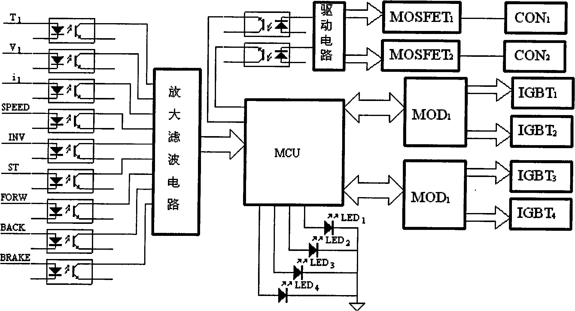
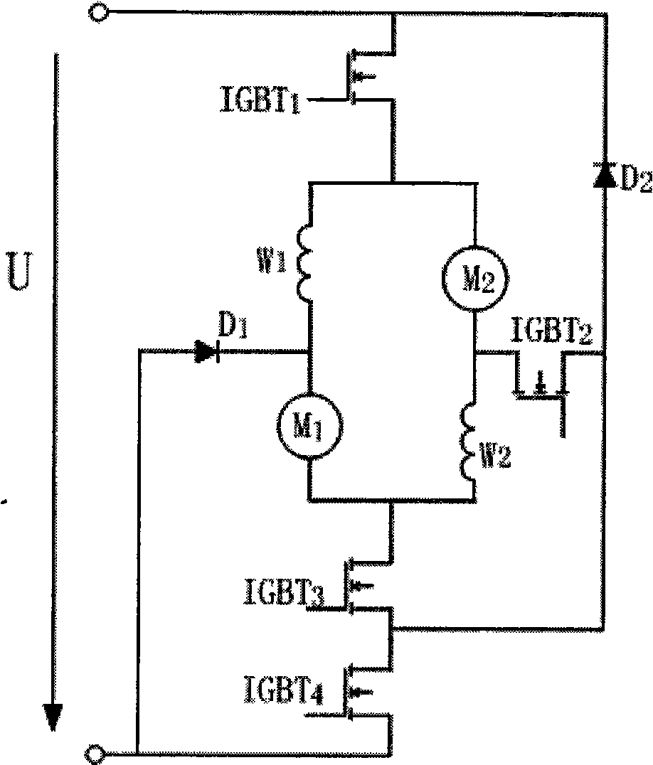
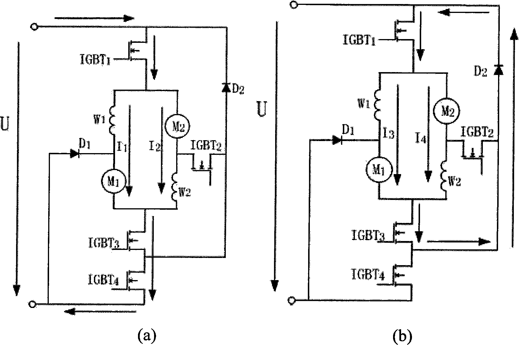
[0034] The schematic diagram of the control circuit of the electric control system is shown in figure 1 shown. The main control chip of the control system adopts microcontroller MCU (single chip microcomputer or digital signal processor DSP), T 1 It is the input signal for measuring the temperature of the IGBT cooling plate of the insulated gate bipolar switch tube, V 1 is the DC supply voltage measurement signal, i 1 The main circuit motor current measurement signal, SPEED is the speed given signal, INV, ST, FORW, BACK, BRAKE are the forward and reverse signals of the motor, emergency start signal, forward, backward and braking control signals, etc., in the control circuit It also includes an isolation circuit and a conditioning circuit (amplification and filtering circuit) for each input signal, so that each measurement and control signal can be correctly input to the microcontroller MCU. Microcontroller controls 4 red light emitting diode LEDs 1 ~LED 4 , showing 4 diff...

Embodiment 2

[0039] The IGBT in the first embodiment 1 ~IGBT 4 These 4 high-power IGBTs are replaced by MOSFETs, and each IGBT can be replaced by multiple parallel MOSFETs according to the actual current in the motor winding. At the same time, the 2-way drive modules of the 4 IGBTs are removed and replaced with MOSFET isolation, drive and protection circuits. Since the price of high-power IGBT and drive circuit is much higher than that of MOSFET and its drive circuit, the cost of electric vehicle control system can be greatly reduced by using MOSFET. At the same time, the conduction voltage drop of MOSFET is also smaller than that of IGBT, and the power consumption of the device itself reduce, which has obvious economic benefits.


PUM


Abstract

The invention discloses a control system with braking function of series excited direct current cross-connected double motor used for electric motor cars, which is characterized by comprising a core cell microcontroller (MCU), a complete signal inputting and conditioning circuit, an output executive circuit, a fault display circuit, an input-output isolating circuit, a power electronic switch, a drive circuit thereof and the like; two series excited direct current motors are crossly connected, namely the single motor self is serially excited and two motors are connected in parallel; the main circuit connection driven by the motors consists of two current fly-wheel diodes, four power switch electronic devices, two contactors, etc. The motor connection mode, main circuit and controller disclosed in the invention can realize the functions of motors of rotating the motors normally and reversely, starting current limit, regulating speed, braking, etc. The motors can realize regenerative braking and has high efficiency, and the whole system has characteristics of perfect control functions, high reliability and the like.

Description

technical field [0001] The invention belongs to the field of motor control, in particular to a series-excited direct-current double motor cross-connection system with braking function and a controller thereof for an electric vehicle. Background technique [0002] Electric vehicles have significant advantages such as low noise, no pollution, and easy operation, and are widely used in factory workshops, golf courses, mines, scenic tourist areas and other places. Electric vehicles are powered by high-efficiency rechargeable batteries, and use electric motors instead of fuel engines. Compared with traditional fuel vehicle power systems, electric motors and transmission systems take up less space, and the less space and weight can be used to compensate for the needs of rechargeable batteries; due to the use of a single electric energy source Compared with hybrid electric vehicles, the electronic control system is greatly simplified, which reduces the cost and can also compensate ...

Claims


Application Information

Patent Timeline
IPC IPC(8): H02P5/685
Inventor 梁得亮刘新正娄建勇鲍伟宏
Owner XI AN JIAOTONG UNIV
Why Eureka
Try Eureka