
Anaerobic built-in zero-valent iron reactor

An anaerobic reactor and zero-valent iron technology, applied in the field of water treatment, can solve problems such as long start-up time, treatment failure, and slow sludge granulation, and achieve the effect of good working performance, small design and stable operation

Inactive Publication Date: 2009-12-02
DALIAN UNIV OF TECH
View PDF0 Cites 27 Cited by
  • Summary
  • Abstract
  • Description
  • Claims
  • Application Information

AI Technical Summary

Problems solved by technology

[0003] However, the following main problems still exist in the application of these reactors: (1) The start-up time is long and the sludge granulation is slow. Generally, it takes 3-6 months to start-up, and it is difficult to meet the requirements of polluting enterprises for treatment within a limited period
(2) It is difficult to control the operating conditions of the reactor, and acidification often occurs, which inhibits the growth of methanogens, resulting in the failure of anaerobic treatment
[0007] However, the main obstacle in the application of this method is the compaction of the iron filings bed
When the zero-valent iron filler is in contact with the air, the rate of iron oxidation by the air is far greater than that of iron in the internal electrolysis, and the rapid generation of rust causes adhesion and blockage between iron filings, making the sewage flow short, reducing the efficiency of sewage treatment, and at the same time rust Attached to the iron surface, preventing its further reaction, leading to the failure of the treatment
Therefore, the internal electrolysis method of zero-valent iron has not been successfully applied in practice.

Method used


Image

  • Anaerobic built-in zero-valent iron reactor
  • Anaerobic built-in zero-valent iron reactor
  • Anaerobic built-in zero-valent iron reactor

Examples


Embodiment Construction

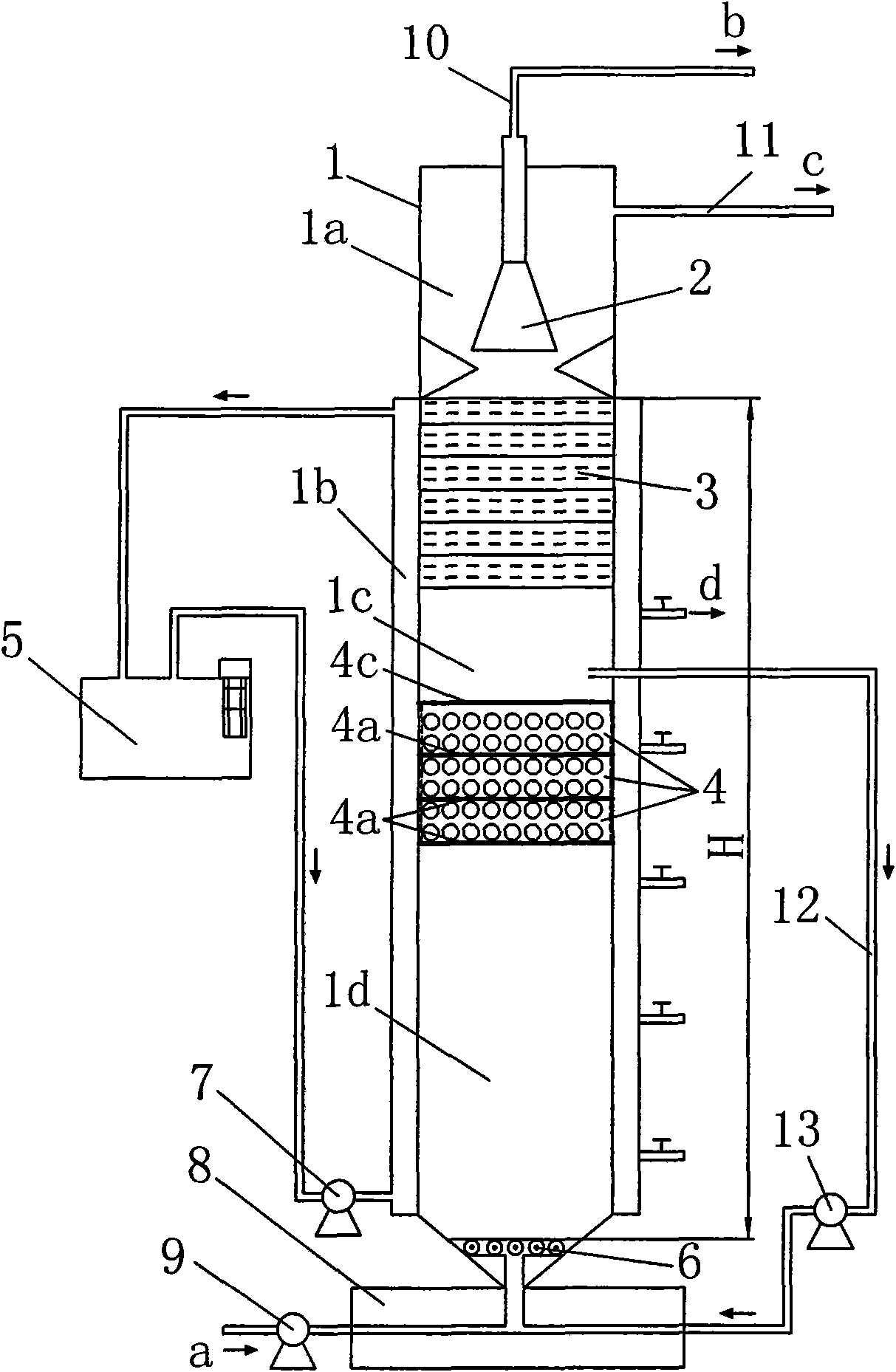
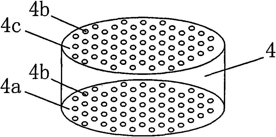
[0021] figure 1 A schematic structural diagram of an anaerobic built-in zero-valent iron reactor is shown. The device mainly includes a cylindrical anaerobic reactor 1. In the anaerobic reactor 1, a water distributor 6, three zero-valent iron filling layers 4, a biological filter layer 3 and a The three-phase separator 2 divides the inner cavity of the anaerobic reactor 1 into a gas-liquid solid separation zone 1a located above the biological filter material layer 3, a suspension zone located between the biological filter material layer 3 and the zero-valent iron filling layer 4 A sludge zone 1c and a sludge expansion zone 1d between the zero-valent iron filling layer 4 and the water distributor 6 . The shell of the anaerobic reactor 1 is made of plexiglass or FRP, with an inner diameter of 90 cm, a height of 120 cm, and an effective volume of 6.36 L. The height of the biological filter material layer 3 and the three-phase separator 2 is 10% of the effective height of the an...


PUM


Abstract

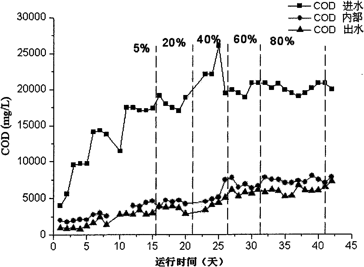
The invention discloses an anaerobic built-in zero-valent iron reactor, which belongs to the technical field of water treatment. The reactor is provided with two to six zero-valent iron packing layers between a water distributor and a biofilter material layer to form a suspended sludge area positioned between the biofilter material layer and the zero-valent iron packing layers and a sludge expansion area positioned between the zero-valent iron packing layers and the water distributor. The suspended sludge area is connected to a water inlet pipeline on the lower part of an anaerobic reactor through a circulating pipeline and a circulating pump. The outside of the anaerobic reactor is provided with a set of hydraulic circulating pipelines to improve the water flow velocity in a carrier sludge layer and the suspended sludge area so as to improve the decomposition rate of anaerobic bacteria on organic substances; the reactor has a reasonable structure and good working performance, can limit the expansion and floating loss of a bottom sludge layer, can improve the degradation capability on the organic substances, achieve high removal rate of the organic substances, and realize the quick startup of sewage at the same time; and late experiments show that the reactor can realize the successful startup of chemical saline wastewater within 43 days and keeps steady operation at subsequent stages.

Description

technical field [0001] The invention relates to an anaerobic built-in zero-valent iron reactor, which belongs to the technical field of water treatment. Background technique [0002] Anaerobic sewage treatment has strong capacity, saves energy, and produces biogas at the same time. It is one of the most promising processes in sewage treatment. After years of development, the anaerobic reactor has developed from the original septic tank to representative USAB (upflow anaerobic sludge bed), EGSB (expanded granular sludge bed), IC (internal circulation anaerobic reactor )Wait. The common characteristics of these third-generation anaerobic reactors are: higher microbial holdings per unit volume, higher hydraulic load, and greatly improved reactor processing capacity. [0003] However, the following main problems still exist in the application of these reactors: (1) The start-up time is long and the sludge granulation is slow. Generally, it takes 3-6 months to start-up, which i...

Claims


Application Information

Patent Timeline
IPC IPC(8): C02F3/28
Inventor 张耀斌荆彦文全燮陈硕
Owner DALIAN UNIV OF TECH
Learn More