Method and device for sintering lime

A calcination device and lime technology, applied in lime production, etc., can solve the problems of low thermal efficiency of the lime kiln system, reduce thermal efficiency and product quality of the lime kiln system, affect productivity, etc., achieve large-scale continuous production, save energy, and improve operations rate effect

Active Publication Date: 2009-12-09
SHIJIAZHUANG XINHUA IND FURNACE CO LTD
View PDF0 Cites 17 Cited by
  • Summary
  • Abstract
  • Description
  • Claims
  • Application Information

AI Technical Summary

Problems solved by technology

Such a process has the following defects. If higher productivity is required, the thermal efficiency and product quality of the entire lime kiln system may be reduced, and i

Method used


Image

  • Method and device for sintering lime
  • Method and device for sintering lime
  • Method and device for sintering lime

Examples


Example Embodiment

[0022] Example 1

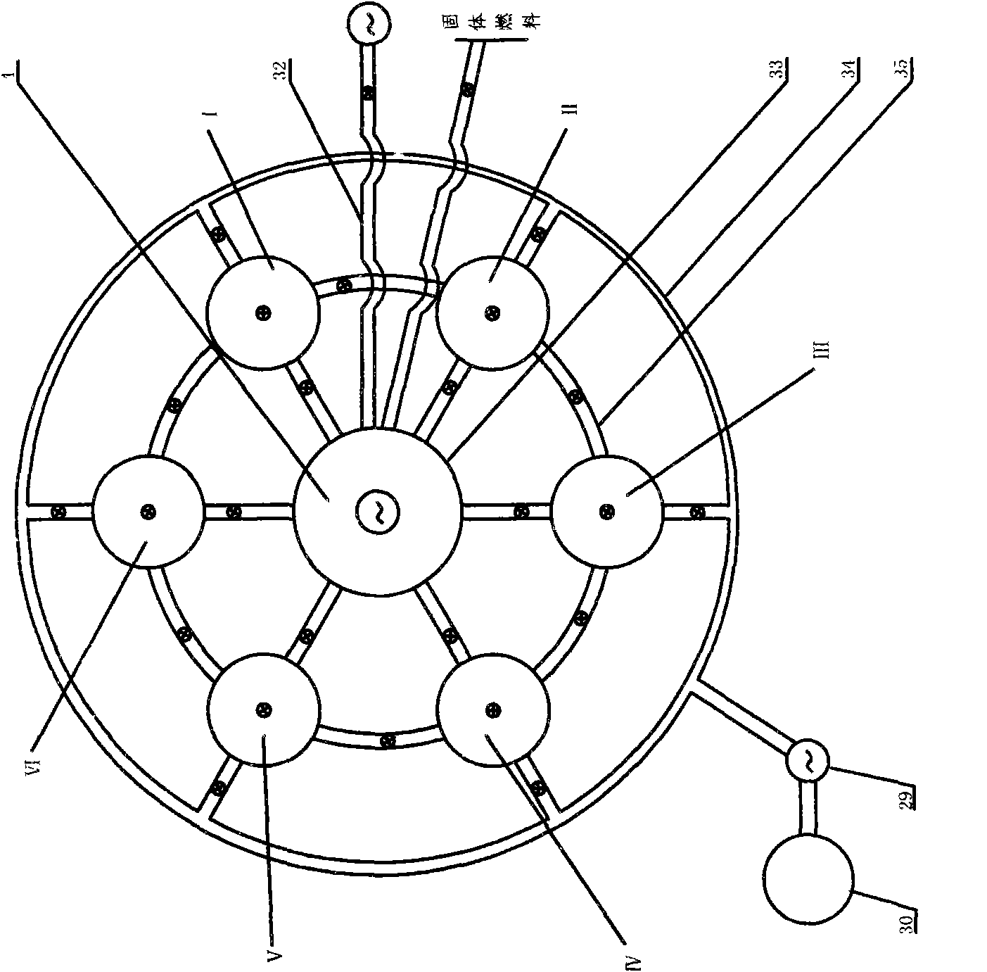
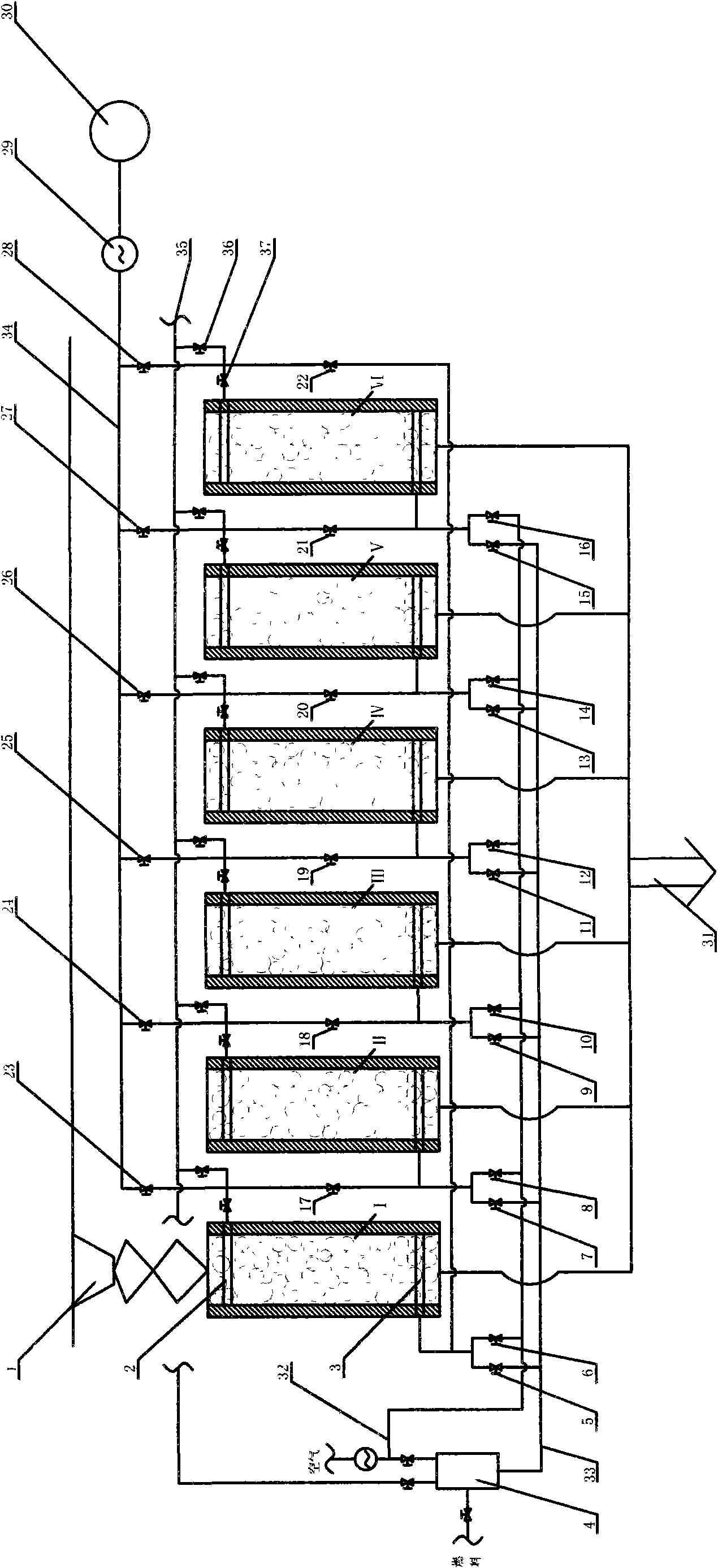
[0023] Examples of the invention are figure 1 , figure 2 , The kiln body is arranged in a ring type. For the sake of simplicity, now figure 2 Shown for description. This system is mainly composed of feeding device 1, kiln body I, II, III, IV, V, VI, combustion chamber 4, unloading device 44, discharge channel 31, flue gas pipeline 33, exhaust gas pipeline 34, air pipeline 32. Shared pipeline 35 and other components. There is a suction beam 2 in the kiln body, and the calcining device is an intake beam 3, the number of which is determined according to the size, height and production load of the lime burning kiln, such as Figure 8 Shown. The valve 36 in the common pipeline 35 is normally closed and the valve 37 is normally open. Only when a certain kiln body is overhauled or the kiln calcination sequence is adjusted, the valve 37 and the valve 36 can be opened and closed accordingly.

[0024] The intake beam 3 is installed in the lower part of the kiln body, o...

Example Embodiment

[0027] Example 2

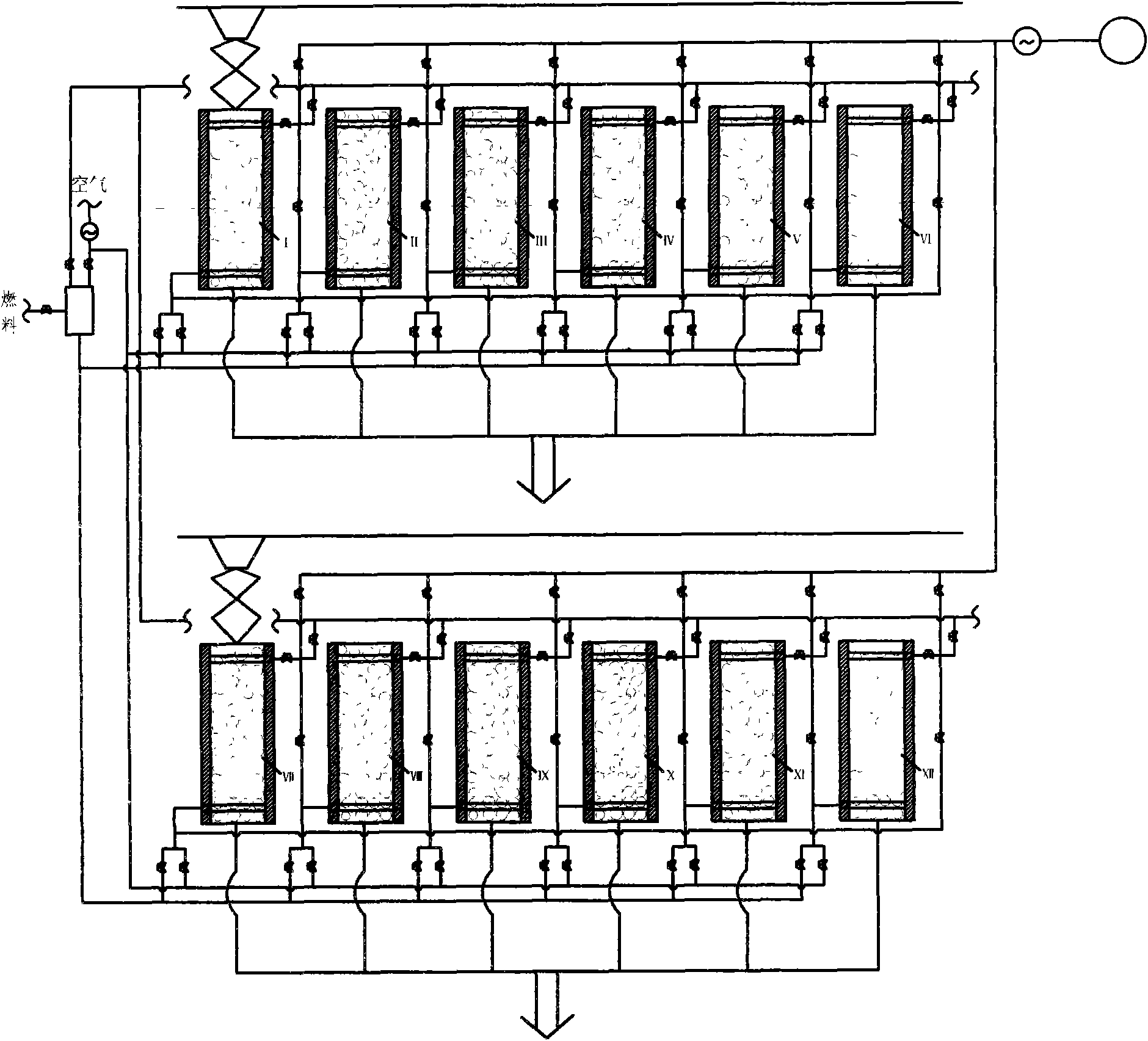
[0028] Examples of the invention are image 3 As shown, the kiln body is arranged in a matrix type. The high-temperature flue gas produced by this system is selectively opened to pass through the valve according to the needs of the entire process, that is, when one or more kiln bodies are calcined, one or more kiln bodies are preheating, and one or more kiln bodies are preheating. During cooling, one or more kiln bodies are producing finished ash and charging limestone.

[0029] The other processes and process conditions of this embodiment are the same as those of embodiment 1.

Example Embodiment

[0030] Example 3

[0031] Examples of the invention are Picture 9 As shown, the calcination device is a combustion beam 45 (such as Picture 10 (Shown), the combustion beam is provided with a burner 48, and the system has a fuel pipeline 47. The working principle of the system is as follows: fuel enters the fuel pipe of the combustion beam 45 through the fuel pipe 47, and the combustion-supporting air enters the air pipe of the combustion beam from the air pipe 32, and mixes and burns the limestone at the burner. The high-temperature flue gas after calcination of limestone exits from the suction beam and enters another limestone kiln body waiting to be preheated to preheat the limestone in the kiln body. The cooling air enters the kiln body from the burner of the combustion beam to cool the calcined lime. The preheated air after cooling the lime product can be used as combustion-supporting gas and enters the combustion beam through the common pipeline 35 for combustion.

[0032] ...


PUM


Abstract

The invention relates to a method and a device for sintering lime. The device comprises a plurality of kilns which are distributed in a ring or matrix or other shapes. Solid fuel such as coal powder, and the like, or gas fuel or liquid fuel, or mixed fuels of solid, gas and liquid combusts in the kilns or a separately arranged combustion chamber, and generated high-temperature smoke sinters limestone in the kilns and preheats the limestone in other kilns. Each kiln is internally provided with an air inlet girder and an up-sucking girder. The top of each kiln is provided with a movable feeding device capable of feeding for each kiln in a system. The bottom of each kiln is provided with a movable discharging device connected with a discharging channel and gathering dust generated by each kiln. By using the method and the device for sintering lime, the limestone can be sintered more sufficiently and evenly and has good quality and high activity degree; and meanwhile, the invention can sufficiently utilize afterheat, save the energy source, improve the thermal efficiency of the system, lower the production cost and realize large-scale continuous production.

Description

technical field [0001] The invention relates to a method and device for calcining materials, in particular to a method and device for burning lime. Background technique [0002] Lime and lightly burned dolomite are important building materials, as well as important raw materials in the fields of metallurgy and chemical industry. In the prior art, limestone and dolomite are used as raw materials, and various fuels are applied to lime kilns to produce lime with existing heating methods in many forms. Such a process has the following defects. If higher productivity is required, the thermal efficiency and product quality of the entire lime kiln system may be reduced, and if the product quality is to meet higher requirements, the productivity will be affected, and the lime kiln system will also be affected. Thermal efficiency is at a low level. Contents of the invention [0003] In order to overcome the deficiencies of the prior art, use waste heat, improve quality, increase ...

Claims


Application Information

Patent Timeline
IPC IPC(8): C04B2/10
CPCY02P40/40
Inventor 贾会平
Owner SHIJIAZHUANG XINHUA IND FURNACE CO LTD
Why Eureka
Try Eureka