Micro nuclear battery with protection ring structure and manufacturing method thereof

A protection ring and nuclear battery technology, which is applied in the fields of semiconductors, nuclear physics and micro-energy, can solve the problems of low sensitivity and energy conversion efficiency, and achieve the effects of improving energy conversion efficiency, increasing open circuit voltage, and increasing sensitivity

Inactive Publication Date: 2009-12-09
江苏福克斯电气集团有限公司 +1
View PDF0 Cites 28 Cited by
  • Summary
  • Abstract
  • Description
  • Claims
  • Application Information

AI Technical Summary

Problems solved by technology

[0006] The purpose of the present invention is to overcome the shortcomings of low sensitivity and energy conversion efficiency caused by the current leakage of existing micro-nuclear batteries, to provide a new micro-nuclear battery structure with smaller leakage current and higher conversion efficiency, and to provide a Easy-to-manufacture preparation method

Method used


Image

  • Micro nuclear battery with protection ring structure and manufacturing method thereof
  • Micro nuclear battery with protection ring structure and manufacturing method thereof
  • Micro nuclear battery with protection ring structure and manufacturing method thereof

Examples


specific Embodiment 1

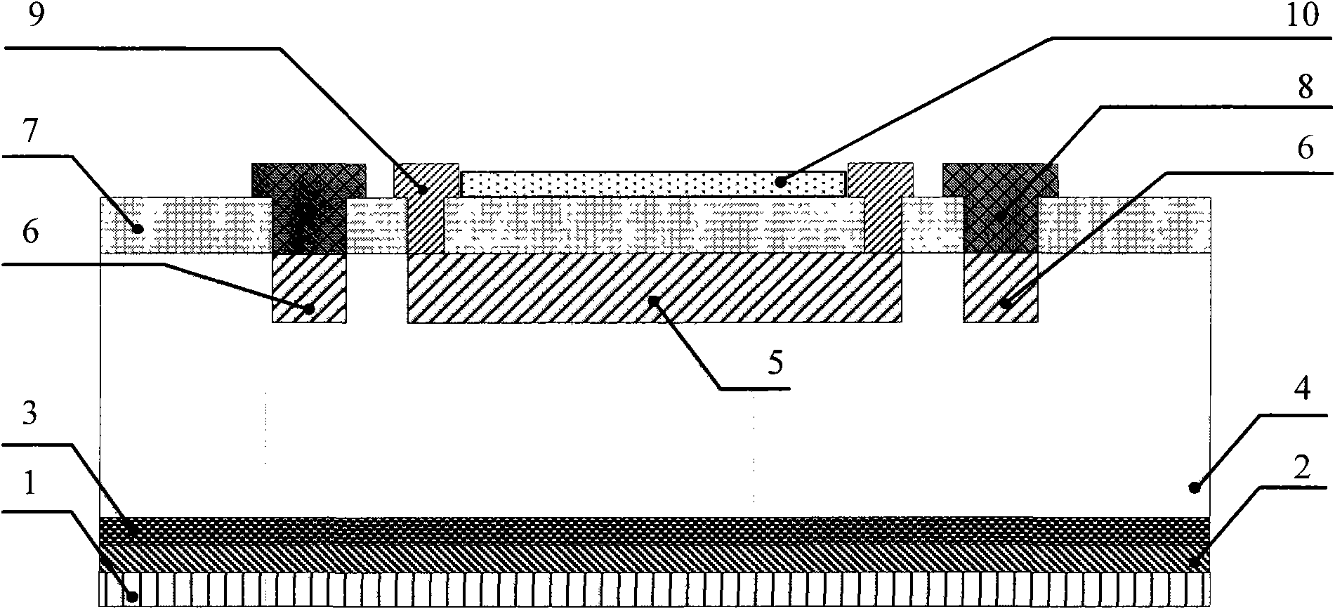
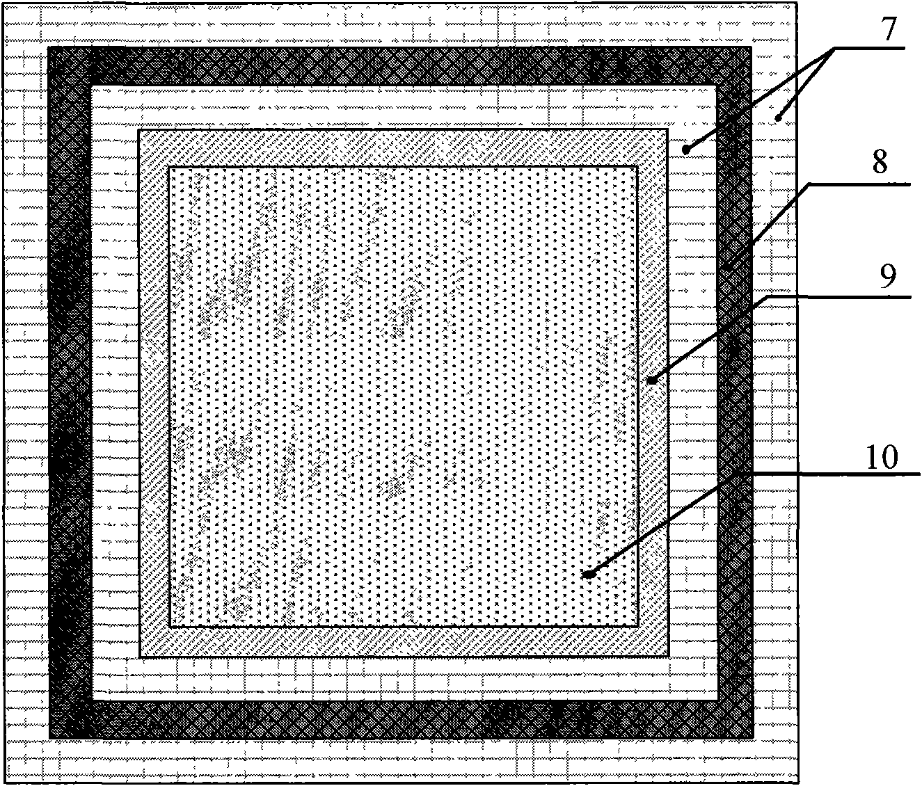
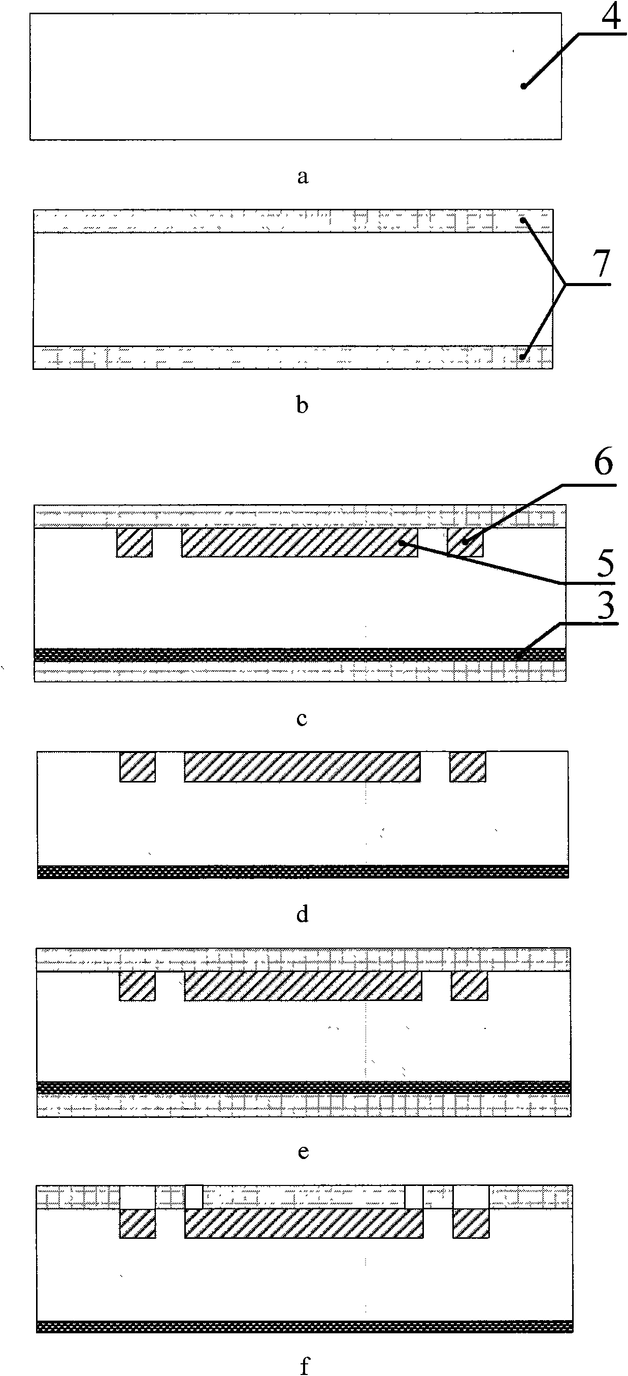
[0039] refer to figure 1 and figure 2 , the present embodiment is a micro-nuclear battery based on a silicon material PIN junction structure with a guard ring, which sequentially includes an isotope 10, an upper electrode metal layer 9, a guard ring contact electrode 8, a passivation layer 7, a guard ring 6, and a p+ type silicon Region 5, intrinsic silicon layer 4, n+ type silicon layer 3, metal adhesion layer 2, bottom electrode metal layer 1. The intrinsic silicon layer 4 has a resistivity of 2000 ohm cm, a thickness of 300 μm, and a square shape; the upper part of the intrinsic silicon layer 4 has a doping concentration of 6×10 20 cm -3 The square area is the p+ type silicon region 5, and its thickness is 1 μm; the guard ring 6 is located on the periphery of the p+ type silicon region 5, forming a square frame of equal thickness including the p+ type silicon region 5, and the material of the guard ring 6 is the same as that of the p+ type silicon region 5. The silicon...

specific Embodiment 2

[0051] refer to Figure 4 and Fig. 5, the present embodiment is a micro-nuclear battery based on a SiC material PN junction structure with a guard ring, which sequentially includes an isotope 10, an upper electrode metal layer 9, a guard ring contact electrode 8, a passivation layer 7, a guard ring 6, p+ type SiC layer 5 , n+ type SiC layer 3 , metal adhesion layer 2 , bottom electrode metal layer 1 . Wherein the doping concentration of n+ type SiC layer 3 is 6×10 17 cm -3 , a thickness of 500 μm, a circular shape; the upper doping concentration of the n+ type SiC layer 3 is 6×10 19 cm -3 , a circular area with a radius of 5.6 mm and a thickness of 0.8 μm is the p+-type SiC layer 5; the guard ring 6 is located on the periphery of the p+-type SiC layer 5, forming an equal-thickness ring including the p+-type SiC layer 5, and the circle The difference between the inner and outer radius of the ring is 100 μm, the material of the guard ring 6 is consistent with the p+ type SiC...


PUM


Abstract

The invention discloses a PN junction or PIN junction type micro nuclear battery and a manufacturing method thereof, belonging to the fields of semiconductor, nuclear physics and micro energy source. The battery is provided with a protection ring 6 in the periphery ring-shaped region of a p+ type semiconductor layer 5 on the basis of traditional PN junction or PIN junction type micro nuclear battery; meanwhile a protection ring contact electrode 8 is arranged above the protection ring 6 for leading an electrical signal out; in addition, the manufacturing method of the nuclear battery is also disclosed. In the micro nuclear battery disclosed by the invention, the added protection ring inhibits surface leakage and influence of interface state current on radiation induced current, indirectly increases open circuit voltage, and also improves sensibility of elements on low-energy radioactive source, thus improving energy conversion efficiency of elements.

Description

technical field [0001] The invention belongs to the fields of semiconductor, nuclear physics and micro-energy, and in particular relates to a PN junction or PIN junction micro-nuclear battery and a preparation method thereof. Background technique [0002] Micro-nuclear batteries can solve the long-term power supply problems of micro-pipe robots, implanted micro-systems, wireless sensor node networks, artificial cardiac pacemakers and portable mobile electronic products; Electric energy is superior to the traditional thermoelectric radioisotope battery (RTG, RadioisotopeThermoelectric Generator) that requires a thermal insulation layer, and is more suitable for miniaturization, light weight and integration, and is expected to replace solar cells and thermoelectric radioisotope batteries in the fields of aerospace and aviation Solve the long-term power supply problems of micro / nano satellites, deep space unmanned probes and ion thrusters. [0003] refer to Figure 7 , the lit...

Claims


Application Information

Patent Timeline
Patent Type & Authority Applications(China)
IPC IPC(8): G21H1/06
Inventor 乔大勇苑伟政臧博姚贤旺吕湘连
Owner 江苏福克斯电气集团有限公司
Why Eureka
Try Eureka