Constant-pressure alcohol-ether hydrazine production process
A production process, the technology of hydrazine, applied in the production process of ether hydrazine and the field of pressing alcohol, can solve the problems of energy consumption, material consumption, low synthesis rate, large amount of released gas, etc., and achieve flexible adjustment, reasonable flow direction, Overcome the effect of low synthesis rate
- Summary
- Abstract
- Description
- Claims
- Application Information
AI Technical Summary
Problems solved by technology
Method used
Image

Examples
Embodiment 1
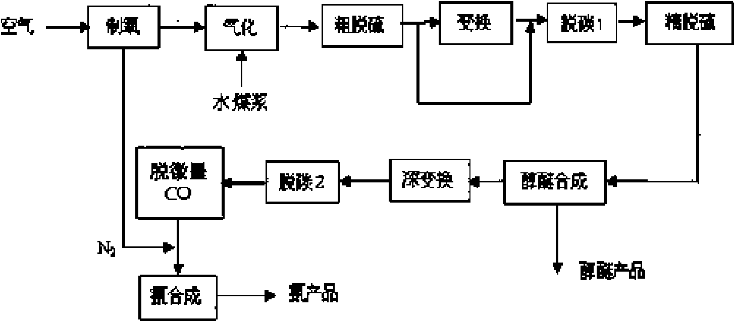
[0025] refer to figure 1 , the semi-water gas with a pressure of 5.5MPa obtained from coal-water slurry plus oxygen pressurized gasification undergoes rough desulfurization, transformation, decarburization 1, and fine desulfurization, then joins the deoiled circulating gas and enters the gas preheater, and synthesizes The hot synthesis gas coming out of the bottom of the tower is heat exchanged in countercurrent, heated to 200-220°C, enters the annulus of the catalyst frame from the bottom of the synthesis tower, and radially enters the catalyst layer between the tubes from the circumferential direction. At 225-255°C, hydrogen and carbon monoxide, Carbon dioxide reacts to form methanol and water. After the reaction, the gas converges in the central gas collecting pipe (temperature is 230-280°C) and then exits the synthesis tower. The gas enters the shell side of the intermediate heat exchanger and exchanges heat with the gas entering the tower. The temperature drops to 78-85°C...
Embodiment 2
[0029] The process of Example 1 was repeated, except that the methanol synthesis part was changed to dimethyl ether synthesis. The dimethyl ether synthesis catalyst used is a copper-based composite catalyst, the reaction temperature is 268° C., and the reaction pressure is 5.0 MPa. Part of the gas after separation of dimethyl ether enters the cycler as a cycle gas, and the other part is sent to the "deep shift" process to convert the CO contained in this part of the tail gas into H 2 and CO 2 , and then into decarburization 2, the contained CO 2 Removal, the residual trace CO in the secondary decarburization gas enters the PSA system and is completely removed. In this way, the purified gas is added with an appropriate amount of pure nitrogen from the nitrogen production process, and the hydrogen-nitrogen ratio of the gas is adjusted to 3, and then synthesized with ammonia. Meet and send to the ammonia synthesis tower, the ammonia synthesis pressure is 5.0MPa, and the space v...
Embodiment 3
[0033] Repeat the process of Example 1, just change the methanol synthesis part into gas-phase fixed bed F-T synthesis, the process pressure is 5.0MPa, the catalyst layer operating temperature is 200 ~ 250 ° C, H 2 / CO ratio is 2.0, airspeed is 10000h -1 . The ammonia synthesis conditions and the adjusted gas composition at the inlet and outlet of the ammonia synthesis tower are the same as in Example 1.
PUM
 Abstract
Description
Claims
Application Information
 - R&D
- Intellectual Property
- Life Sciences
- Materials
- Tech Scout
- Unparalleled Data Quality
- Higher Quality Content
- 60% Fewer Hallucinations
Browse by: Latest US Patents, China's latest patents, Technical Efficacy Thesaurus, Application Domain, Technology Topic, Popular Technical Reports.
© 2025 PatSnap. All rights reserved.Legal|Privacy policy|Modern Slavery Act Transparency Statement|Sitemap|About US| Contact US: help@patsnap.com