Field measurement device of wave aberration of projection objective in photo-etching machine

A projection objective lens and on-site measurement technology, applied in the field of optical measurement, can solve problems such as the decrease of transmittance and the impact on measurement accuracy, and achieve the effects of high absolute measurement accuracy, cost reduction, and easy integration

Active Publication Date: 2009-12-23
BEIJING INSTITUTE OF TECHNOLOGYGY
View PDF2 Cites 14 Cited by
  • Summary
  • Abstract
  • Description
  • Claims
  • Application Information

AI Technical Summary

Problems solved by technology

[0008] 3) The device uses the pinhole on the mask table to select and measure the field of view point and filter to eliminate the wavefront error of the illumination system, and the device needs to deviate the pinhole in front of the collimating objective lens from the mirror surface of the projection object when calibrating the system error, and again Filtering is performed to generate spherical waves to calibrate the system error of the measurement device. After two filterings, the transmittance of the system decreases. As the numerical aperture of the projection objective increases, the pinhole size becomes smaller and smaller, which further reduces the transmittance. , will affect the measurement accuracy

Method used


Image

  • Field measurement device of wave aberration of projection objective in photo-etching machine
  • Field measurement device of wave aberration of projection objective in photo-etching machine
  • Field measurement device of wave aberration of projection objective in photo-etching machine

Examples


Embodiment Construction

[0035] The present invention will be further described below in conjunction with the accompanying drawings and specific embodiments.

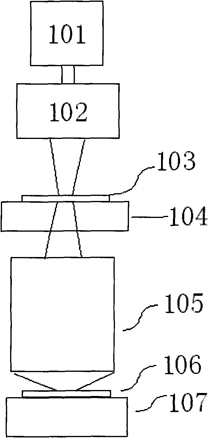
[0036] First introduce the lithography machine system, its composition block diagram is as follows figure 1 As shown, it includes: a light source 101 , an illumination system 102 , a mask 103 , a mask stage 104 , a projection objective lens 105 , a silicon wafer 106 and a silicon wafer stage 107 .

[0037] The working principle of the lithography machine is as follows: after passing through the illumination system 102, the light emitted by the light source 101 is irradiated on the mask 103, and the pattern on the mask 103 is passed through the projection objective lens 105, and the projection is reduced in a "step-scan" manner. On the silicon wafer 106 coated with photoresist, so as to realize the pattern transfer. Wherein, the light source 101 is an excimer laser light source, such as an ArF excimer laser with a wavelength of about 193 nm or ...


PUM


Abstract

The invention relates to a field measurement device of wave aberration of a projection objective in a photo-etching machine. The device is based on the shack-hart mann measurement principle, and comprises a host machine and a standard lens, wherein the host machine comprises a photoelectric sensor, a diffraction optical element, a collimator objective, a pinhole maskplate provided with a round hole, and a beam splitting device used for controlling light path transmission; the standard lens includes a first standard lens used for folding back light path when in systematic error of the demarcated host machine, and a second standard lens used for folding back the light path when the wave aberration of the projection objective is measured by the host machine. The host machine and the first standard lens are integrated on a reticle mask stage of the photo-etching machine, and the second standard lens is integrated on a silicon chip stage; when in measurement, the silicon chip stage and the reticle mask stage are moved to the measuring position for measuring and correcting the wave aberration of full view field of the projection objective in the photo-etching machine. The field measurement device has higher absolute measuring accuracy, is suitable for the field measurement of the wave aberration of the projection objective in the photo-etching machine, reduces the cost, the volume and the weight of the device, and is convenient for integration.

Description

technical field [0001] The invention relates to a device for on-site measurement of the optical performance of a projection optical system, in particular to an on-site measurement device for the wave aberration of a projection objective lens of a lithography machine, belonging to the technical field of optical measurement. Background technique [0002] In the manufacturing process of large-scale integrated circuits, a photolithography machine with a projection exposure device is usually used to reduce and project the pattern on the mask on a silicon wafer coated with photoresist through a projection objective lens. At present, ArF lithography technology, the mainstream technology of lithography equipment, has been developed to a technology node below 65nm. In order to meet the requirements of low process factor ArF lithography technology feature size control, the wave aberration of high numerical aperture projection objective lens system usually needs to be controlled Within...

Claims


Application Information

Patent Timeline
Patent Type & Authority Applications(China)
IPC IPC(8): G03F7/20G01M11/02
Inventor 刘克李艳秋刘丽辉汪海
Owner BEIJING INSTITUTE OF TECHNOLOGYGY
Why Eureka
Try Eureka