Direct-current (DC) restoration and DC monitoring circuit

A DC recovery and monitoring circuit technology, applied in the field of optical communication, can solve problems such as inability to monitor optical power

Inactive Publication Date: 2010-01-06
TIANJIN VAST TECH
View PDF0 Cites 11 Cited by
  • Summary
  • Abstract
  • Description
  • Claims
  • Application Information

AI Technical Summary

Problems solved by technology

However, its DC recovery current is not exactly equal to the input DC photocurrent, and the error between its monitoring current and input photocurrent is generally about 10%.
Due to the limitation of monitoring current accuracy, the monitoring function of existing chips can only be used for optical unity, and cannot be used for optical power monitoring.

Method used


Image

  • Direct-current (DC) restoration and DC monitoring circuit
  • Direct-current (DC) restoration and DC monitoring circuit

Examples


Embodiment Construction

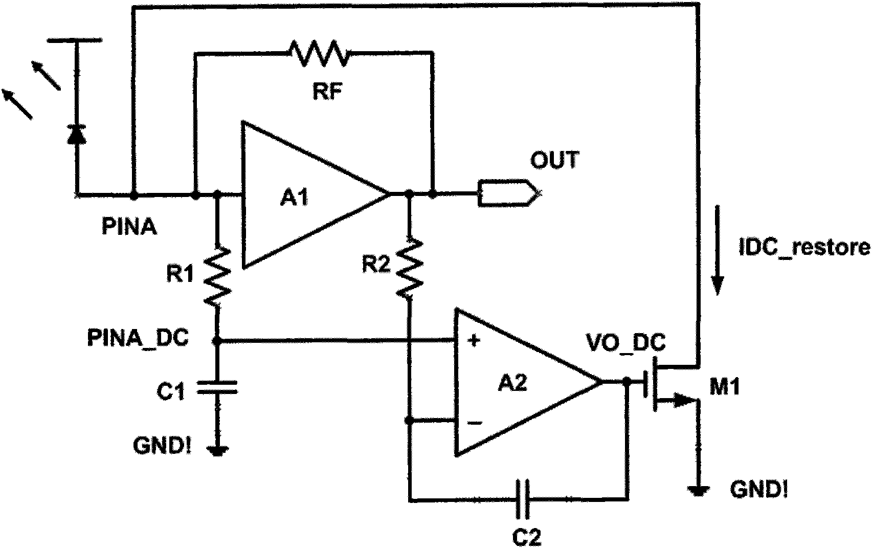
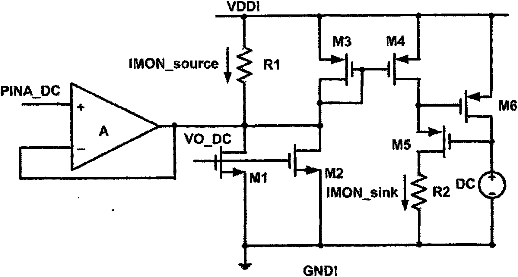
[0023] A DC restoration and monitoring circuit comprising the following circuits

[0024] A transimpedance amplifier converts the current flowing through the photodetector into a voltage for output.

[0025] A DC restoration circuit for bypassing the DC current flowing through the photodetection device.

[0026] The DC monitoring circuit monitors the DC current flowing through the photodetector.

[0027] The integrator is connected with the DC restoration circuit and the monitoring circuit, provides high low-frequency gain for the monitoring circuit and the DC restoration circuit, and forms a buffer at high frequency.

[0028] The Wilson current mirror is connected with the DC monitoring circuit, and replicates the DC current obtained by the monitoring circuit with high precision, so as to provide the possibility to monitor the photocurrent by adopting the current sink structure.

[0029] Current sink or current source monitoring circuit, in order to facilitate the user to p...


PUM


Abstract

The invention relates to a direct-current (DC) restoration and DC monitoring circuit comprising a transimpedance amplifier, a DC restoration circuit and a DC monitoring circuit. The transimpedance amplifier is connected with the DC restoration circuit and the DC monitoring circuit, and the integrator theory is applied to the DC restoration circuit and the DC monitoring circuit. The gain of an integrator at a low-frequency stage can achieve the open loop gain of an operational amplifier and ensures an input DC current to completely flow through the DC restoration circuit but not flow through the transimpedance amplifier; the gain of the integrator is extremely low at a high-frequency stage and can not generate great influence on signal amplification. A Wilson current mirror is applied to copy a monitoring current and ensures that the error of the copied current is smaller than 2 per thousand, in addition, the output of the monitoring current can be a current sink or a power supply.

Description

technical field [0001] The invention belongs to the field of optical communication and integrated circuit design, in particular to a DC restoration and DC monitoring circuit. Background technique [0002] Fiber optic communication uses light as the information carrier and optical fiber as the transmission medium. At present, the bottleneck of the development of the optical communication industry. Microelectronic integrated circuits used in optical communication networks mainly include preamplifiers, limiting amplifiers, clock and data recovery circuits, splitters, and multiplexers. The preamplifier is directly connected to the photodetection device, and the photodetection device converts the input optical signal into a current, and the current signal is amplified by the pre-transimpedance amplifier to obtain a corresponding voltage signal. Since the preamplifier requires low noise and high bandwidth, the preamplifier generally adopts a transimpedance amplifier design. The...

Claims


Application Information

Patent Timeline
Patent Type & Authority Applications(China)
IPC IPC(8): H02M3/156
Inventor 李景虎王永生喻明艳
Owner TIANJIN VAST TECH
Why Eureka
Try Eureka