Method and device for implanting heavy ion beams into synchrotron

A technology of synchrotron and heavy ion beam, which is applied in the direction of magnetic resonance accelerators, accelerators, electrical components, etc., can solve the problems of high precision in the production of electrostatic deflection plates, the inability to change the ion charge state, and low injection efficiency, etc., to achieve operation Stability, long life, and high injection efficiency

Active Publication Date: 2010-01-20
INST OF MODERN PHYSICS CHINESE ACADEMY OF SCI
View PDF1 Cites 19 Cited by
  • Summary
  • Abstract
  • Description
  • Claims
  • Application Information

AI Technical Summary

Problems solved by technology

[0004] The disadvantage of this injection mode is that the efficiency of multi-turn injection is very low, and the manufacturing precision of the electrostatic deflection plate nec...

Method used


Image

  • Method and device for implanting heavy ion beams into synchrotron
  • Method and device for implanting heavy ion beams into synchrotron
  • Method and device for implanting heavy ion beams into synchrotron

Examples


Embodiment 2

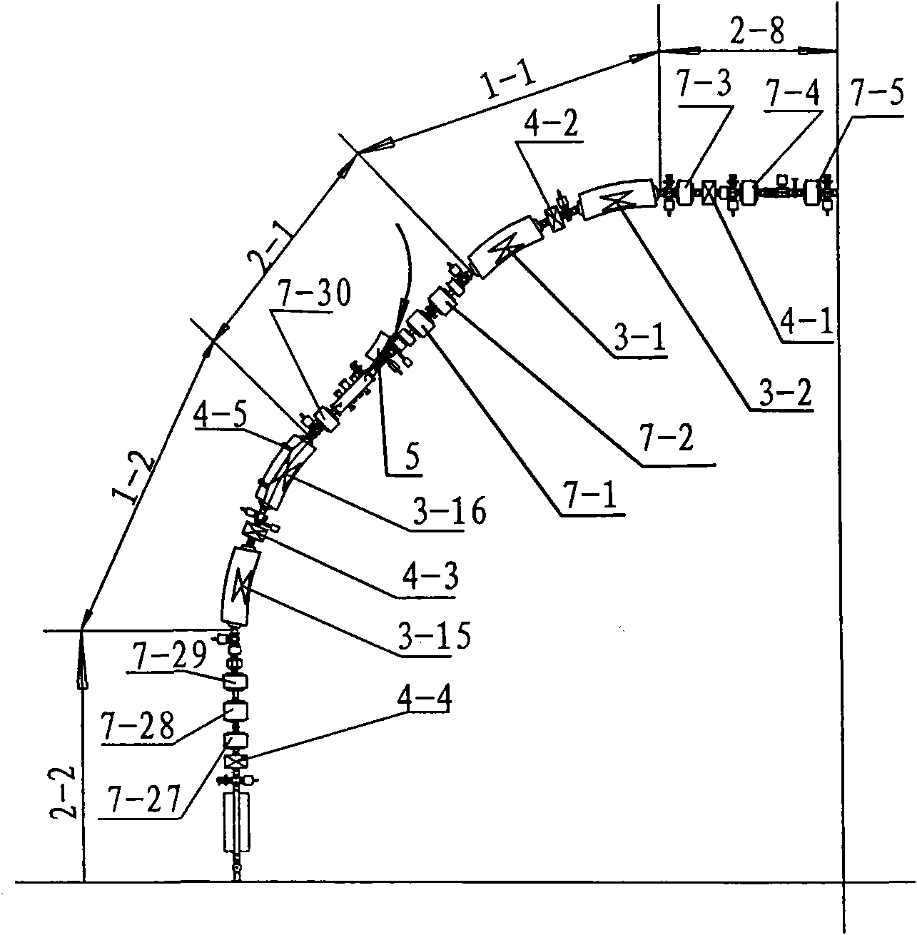
[0034] Example 2: see figure 1 , with figure 1 is the injection segment in the synchrotron. A device for injecting a heavy ion beam into a synchrotron, comprising curved sections 1-1 and 1-2 at both ends of the injection device 2-1, and a straight line section 2-2 downstream of the curved section 1-2 , a straight line section 2-8 is provided upstream of the curved section 1-1.

[0035] Described curve segment 1-1 comprises dipole magnet 3-1, 3-2, and described curve segment 1-2 comprises dipole magnet 3-15, 3-16; In two dipole magnets 3-1 , 3-2 is provided with kick rail magnet 4-2, is provided with kick rail magnet 4-3 between two two pole magnets 3-15,3-16; Straight line section 2-2 includes quadrupole magnet 7- 27,7-28,7-29 and kick rail magnet 4-4, straight line section 2-8 includes four-stage magnet 7-3,7-4,7-5 and kick rail magnet 4-1; 3-16 is provided with a peeling film 4-5; a cutting magnet 5 and quadrupole magnets 7-1, 7-2, 7-30 are provided in the straight secti...

Embodiment 3

[0036] Embodiment 3: The peeling film is a carbon film prepared by a DC arc discharge method. When the incompletely stripped heavy ion beam passes through the stripped film, some or all of the electrons outside the nucleus will be lost, and the number of lost electrons is related to the thickness of the film. The design of the release film ended up with the following characteristics:

[0037] 1. It has a large effective area, and the maximum effective area of ​​the finally developed release film is 40×40mm 2 .

[0038]2. In order to release the film itself without affecting the track of the stored ions, the release film adopts a U-shaped target frame, and the width of the frame is less than 2mm.

[0039] 3. In order to improve the uniformity of the film, so that the energy of the ions after stripping has less dispersion. The release film adopts a double-layer structure.

[0040] 4. According to the energy of different implanted ions and the requirements for the charge stat...

Embodiment 4

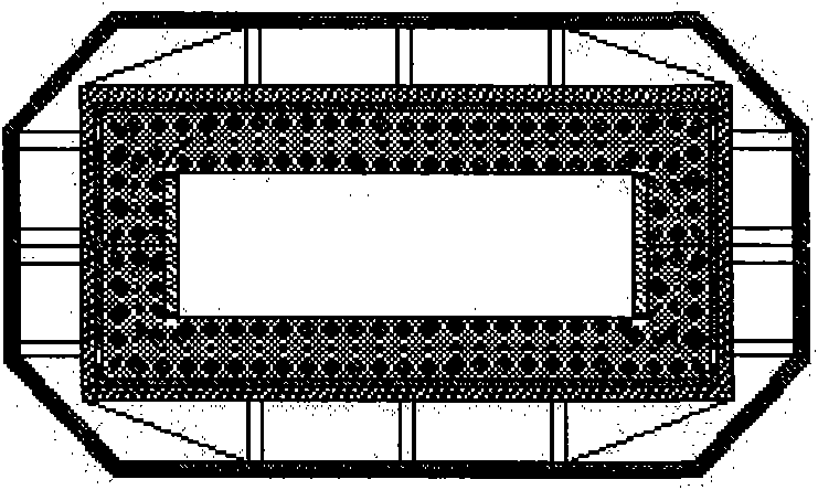
[0041] Example 4: image 3 It is a schematic diagram of a kicking magnet. In order to reduce the eddy current loss, the iron core is generally made of ferrite material. A layer of 5mm thick copper shielding shell is added to the steel structure shell of the magnet. In addition, since the magnetic field works in a very fast pulsed manner, a special ceramic vacuum chamber is used to eliminate the eddy currents generated by the pulsed magnetic field on the walls of the vacuum chamber.


PUM

PropertyMeasurementUnit
Widthaaaaaaaaaa

Abstract

The invention mainly relates to a method and a device for implanting non-full stripping heavy ion beams which are provided by a cyclotron and have mass numbers less than or equal to 40 into a synchrotron. The method comprises the following steps: 1. accelerating the heavy ion beams which are not fully stripped and have mass numbers less than or equal to 40 until the energy is 5.0-10.0MeV/u and the intensity of the heavy ion beams is 2.0-6.0mu A; 2. deflecting the heavy ion beams with mass numbers less than or equal to 40 in the step 1 to a stripping foil and embossing the central track of the synchrotron to the position of the stripping foil in the position of an implanting point; 3. reducing the embossment of the central track in the step 2, implanting the stripped heavy ion beams to fill in the space of the synchrotron and enabling the heavy ion beams to carry out cyclotron in the synchrotron. The invention also provides the device for implanting the heavy ion beams into the synchrotron. The device has the advantages of simple device, convenient operation and high implantation efficiency and can realize multiple choices of the charge states of the heavy ion beams by adjusting the thickness of the stripping foil.

Description

Technical field: [0001] The invention mainly relates to a method and a device for injecting a non-fully stripped heavy ion beam current provided by a cyclotron into a synchrotron with a mass number less than or equal to 40. Background technique: [0002] Due to the characteristics of inverted depth dose distribution (Bragg peak), small side scattering, high relative biological effect (RBE) and low oxygen enhancement ratio (OER) in proton and heavy ion beam irradiation, protons, heavy ions Beam cancer treatment has become an advanced and effective cancer radiotherapy method in the world today. At present, only a few developed countries and my country have carried out corresponding research. The results of preliminary clinical treatment trials have shown that proton and heavy ion beams have very significant curative effects in cancer treatment, and there are no obvious toxic and side effects. [0003] The Chinese Patent Publication No. 200580019535 describes that currently, t...

Claims


Application Information

Patent Timeline
IPC IPC(8): H05H13/04
Inventor 夏佳文原有进
Owner INST OF MODERN PHYSICS CHINESE ACADEMY OF SCI
Why Eureka
Try Eureka