
Method for separating and recycling CO2 from mixed gas containing CO2

A technology of separation and recovery, mixed gas, applied in separation methods, dispersed particle separation, chemical separation, etc., can solve the problems of high operating pressure, increased energy consumption, etc., and achieve the effect of saving compression power consumption and excellent solubility

Inactive Publication Date: 2011-09-21
BEIJING UNIV OF CHEM TECH
View PDF3 Cites 0 Cited by
  • Summary
  • Abstract
  • Description
  • Claims
  • Application Information

AI Technical Summary

Problems solved by technology

[0006] The above patents mainly focus on CO 2 The purification of the mixed gas requires a higher operating pressure, and the mixed gas needs to be pressurized before entering the absorption tower, which increases the separation of CO 2 energy consumption; in addition, removal of CO 2 The purified gas and the CO flashed out 2 The air flow is all directly out of the process

Method used


Image

  • Method for separating and recycling CO2 from mixed gas containing CO2
  • Method for separating and recycling CO2 from mixed gas containing CO2
  • Method for separating and recycling CO2 from mixed gas containing CO2

Examples


Embodiment 1

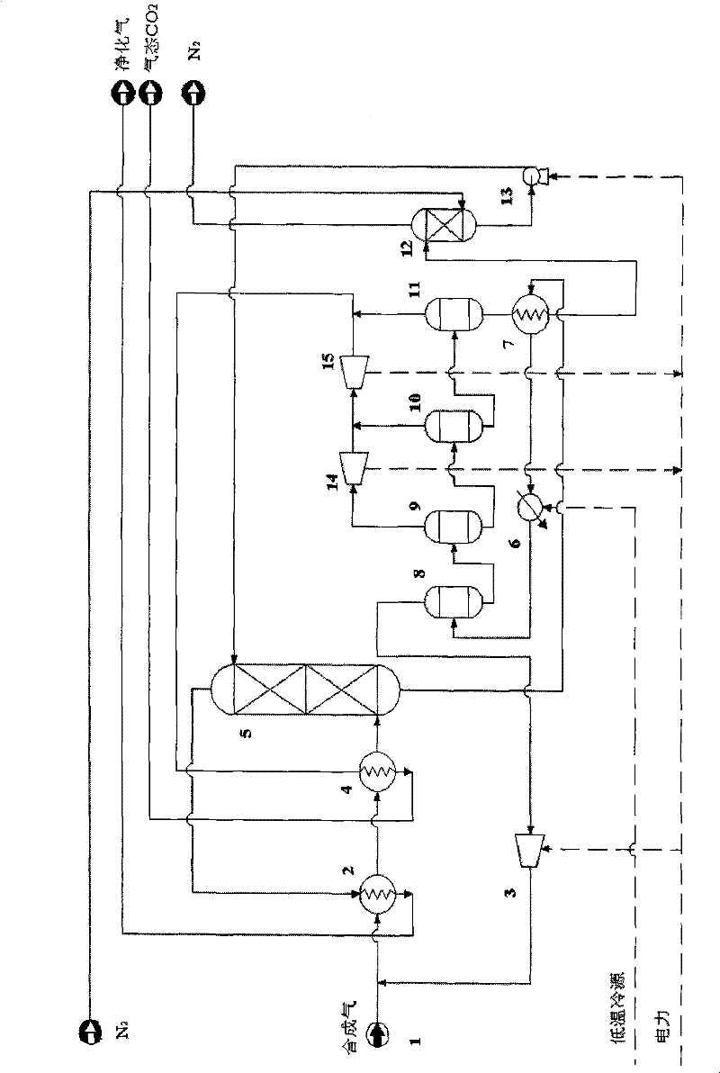
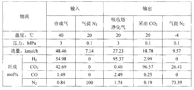
[0020] Embodiment 1: This embodiment is the synthesis gas CO with butyl ether as absorbent 2 Gas recovery process. The raw material mixture gas is synthetic gas, the temperature and pressure are 40°C and 3MPa respectively; it mainly contains CO 2 (42.69%) and H 2 , with a small amount of N 2 and CO. process such as Figure 1 depicts Said:

[0021] (1) Absorption process: The feed gas with a flow rate of 48.46 kmol / h is cooled to 10° C. through heat exchanger I2 and heat exchanger II4, and enters the bottom of absorption tower 5 . Under the operating pressure of 3MPa, the absorbent butyl ether with a flow rate of 48.12kmol / h enters from the top of the absorption tower 5; the purified gas separated from the top of the absorption tower 5 passes through the heat exchanger I2 to recover cooling capacity; 5 The bottom of the tower is rich in CO 2 liquid flow.

[0022] (2) Analysis process: rich CO 2 The liquid flow passes through heat exchanger III7 and cooler 6, and enters...

Embodiment 2

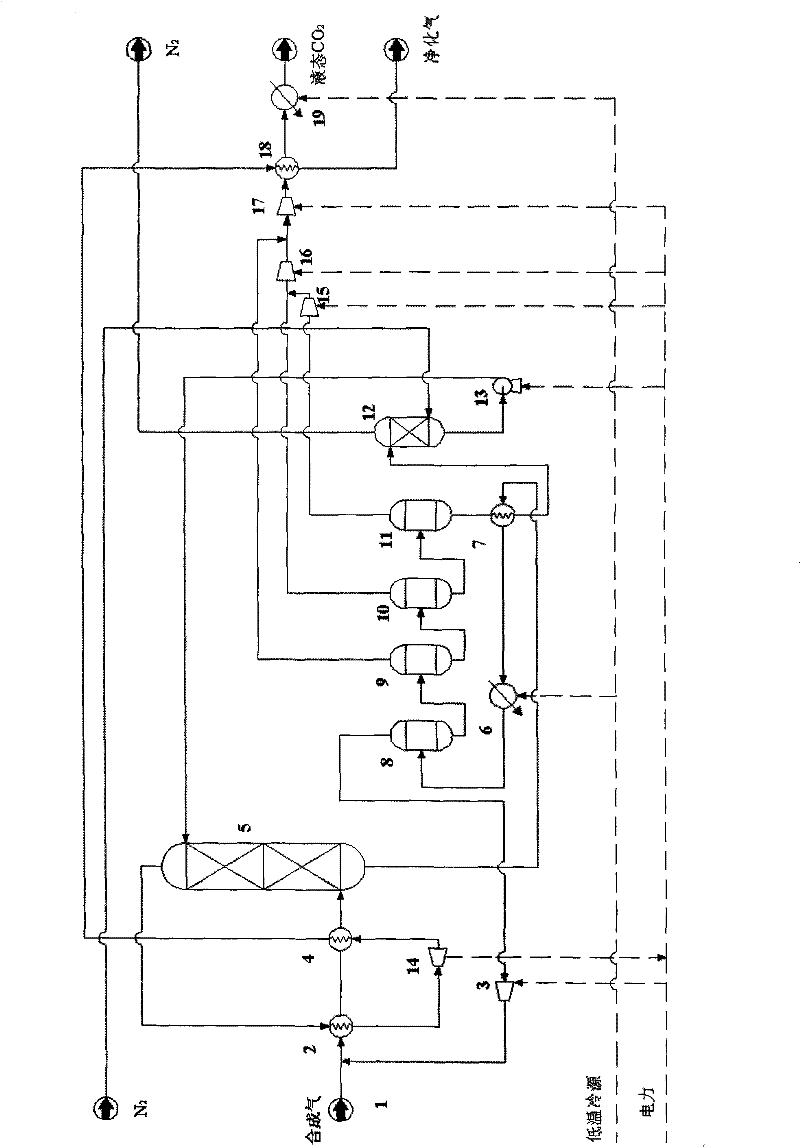
[0027] Embodiment 2: This embodiment uses the mixture of isopropyl ether and butyl ether (molar ratio 1:9) as the gas purification process of the integrated coal gasification combined cycle of the absorbent, and carries out the pre-combustion CO 2 catch. The raw material mixture gas is synthetic gas, the temperature and pressure are 40°C and 3MPa respectively; it mainly contains CO 2 (42.69%) and H 2 , with a small amount of N 2 and CO. process such as Figure 2 depicts Said:

[0028] (1) Absorption process: The feed gas with a flow rate of 48.46 kmol / h is cooled to 10° C. through heat exchanger I2 and heat exchanger II4, and enters the bottom of absorption tower 5 . Under the operating pressure of 3MPa, the flow rate is 39.34kmol / h. The absorbent enters from the top of the absorption tower 5; the purified gas separated from the top of the absorption tower 5 passes through the heat exchanger I2 to recover the cooling capacity once, and recovers it through the expander I14...


PUM


Abstract

The invention relates to a method for separating and recycling CO2 from mixed gas containing CO2, comprising a CO2 separation process and a novel absorbent, wherein, the separation process is composed by gas absorption technology, four-stage flash evaporation deabsorption technology and N2 air stripping absorbent regeneration technology, and the novel absorbent is composed by one or any two of normal or isomeric propyl ether, butyl ether and amyl ether. By adopting the absorbent and process in the invention, the content of CO2 in the purified gas can reach below 0.4%; the purity of extracted CO2 can reach over 96.5%; and the recovery rate of CO2 in the raw material mixed gas can reach over 86%. In the invention, the operating pressure of the process is normally 2.0 MPa to 4.0 MPa, and generally the virgin gas does not need to be pressurized, thus being capable of saving compression energy consumption. Cold energy recovery and excess pressure power recovery are carried out on the extracted gas flow in the invention, thus saving the separation energy consumption of CO2 and realizing the gas purification with low consumption and the liquid collecting of CO2.

Description

Technical field: [0001] The present invention proposes a method for separating CO from mixed gas 2 process method. Suitable for CO containing 2 , CO, hydrogen and nitrogen and other components of the mixed gas, CO 2 separated to obtain CO-free 2 Purified gas, or to obtain liquid CO 2 ; or at the same time. is a CO removal 2 The mixed gas purification process method is also a CO 2 capture process. Background technique: [0002] The technologies relevant to the present invention mainly contain: [0003] 1. CN 1218711A, 1999, the invention uses a mixture of n-formylmorpholine and n-acetylmorpholine as an absorbent, and removes CO in an absorber with an operating pressure of 1MPa to 15MPa. 2 and acid gas components such as sulfur compounds. This method is used to remove CO from industrial gases, especially from natural gas and raw synthesis gas 2 and sulfur compounds. [0004] 2. CN 1356158A, 2002, the invention uses polyethylene glycol dimethyl ether as the absorben...

Claims


Application Information

Patent Timeline
Patent Type & Authority Patents(China)
IPC IPC(8): B01D53/62B01D53/78B01D3/06B01D53/96
CPCY02C10/04Y02A50/20Y02C20/40Y02P70/10
Inventor 郑丹星郭亮武向红董丽
Owner BEIJING UNIV OF CHEM TECH
Learn More