Method and device for treating dye wastewater employing periodic reverse electrocoagulation

A technology of dye wastewater and electrocoagulation, applied in water/sewage treatment, chemical instruments and methods, textile industry wastewater treatment, etc., to achieve the effects of simple operation management, simple system maintenance, and reduced power consumption

Inactive Publication Date: 2010-02-03
NORTHEASTERN UNIV
View PDF0 Cites 10 Cited by
  • Summary
  • Abstract
  • Description
  • Claims
  • Application Information

AI Technical Summary

Problems solved by technology

[0006] Aiming at the deficiencies in the current dye wastewater treatment technology, the present invention provides a method for periodic commutation electrocoagulation treatment of dye wastewater

Method used


Image

  • Method and device for treating dye wastewater employing periodic reverse electrocoagulation
  • Method and device for treating dye wastewater employing periodic reverse electrocoagulation

Examples


Embodiment 1

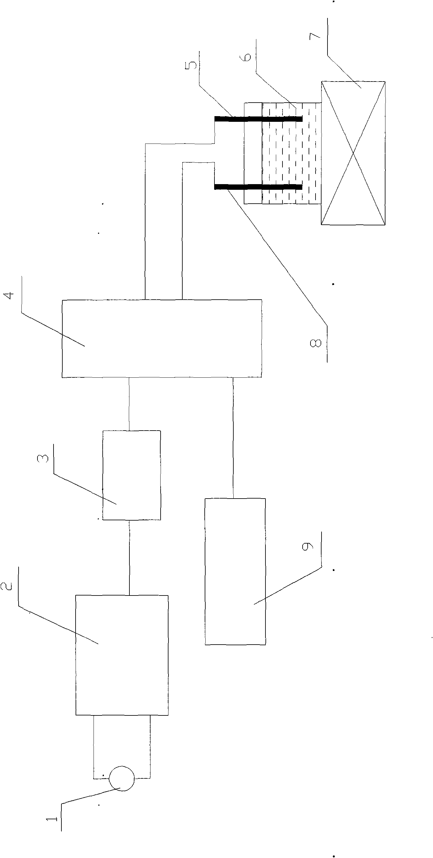
[0027] Introduce the dye wastewater into the electrolytic cell, and add electrolyte to the wastewater in the electrolytic cell to make the electrolyte concentration 0.01mol / L, turn on the stirrer, control the stirring rate to 1000 rpm, control the electrode voltage to 8V, and control the current commutation cycle: 10 Seconds, adjust the pH value of the wastewater to 5, electrolytically treat it for 30 minutes, and then discharge the treated water. The electrolyte is Na 2 SO 4 .

[0028] After analysis, the chroma of the effluent is 0.028 (10 times), the COD is 45mg / L, and the removal rates of the two are 99.6% and 71.5% respectively.

[0029] The power consumption is 0.024KWh / Kg dye.

Embodiment 2

[0031] Introduce the dye wastewater into the electrolytic cell, and add electrolyte to the wastewater in the electrolytic cell to make the electrolyte concentration 0.015mol / L, turn on the stirrer, control the stirring rate to 750 rpm, control the electrode voltage to 13V, and control the current commutation cycle: 20 seconds, adjust the pH value of the wastewater to 7, electrolytically treat it for 30 minutes, and then discharge the treated water. The electrolyte is Na 2 SO 4 .

[0032] After analysis, the chroma of the effluent is 0.067 (24 times), the COD is 55mg / L, and the removal rates of the two are 99.04% and 65.2% respectively.

[0033] The power consumption is 0.046KWh / Kg dye.

Embodiment 3

[0035] Introduce the dye wastewater into the electrolytic cell, and add electrolyte to the wastewater in the electrolytic cell to make the electrolyte concentration 0.008mol / L, turn on the stirrer, control the stirring rate to 1250 rpm, control the electrode voltage to 11V, and control the current commutation cycle: 6 Seconds, adjust the pH value of the wastewater to 6, electrolytically treat it for 40 minutes, and then discharge the treated water. The electrolyte is Na 2 SO 4 .

[0036] After analysis, the chroma of the effluent is 0.110, the COD is 20mg / L, and the removal rates of the two are 96.34% and 80% respectively.

[0037] The power consumption is 0.040KWh / Kg dye.


PUM


Abstract

A method and a device for treating dye wastewater employing periodic reverse electrocoagulation, the reaction electrodes of the device electrolytic cell are aluminum plate and iron plate, and a periodic reverse power supply is used for power supply. The method for treating dye wastewater comprises the following steps: introducing dye wastewater in the electrolytic cell, adding electrolyte in the electrolytic cell to ensure that the concentration of electrolyte is 0.008-0.015mol / L, starting a stirrer, controlling the mixing speed to 750-1250rpm, the electrode voltage to 8-13V and the current commutation cycle to 6-20 seconds, adjusting the pH value of the wastewater to 5-9, electrolyzing for 30-50min, and then discharging the treated water. The system of the invention has compact structure,small floor space and simple operation management and system maintenance, and is easy to realize automatic control. By using the method of the invention to treat dye wastewater, the chroma removal rate can reach above 96% and COD in the treated wastewater can reach the requirement of the grade A discharge standard of The Integrated Wastewater Discharge Standard (GB8978-1996).

Description

technical field [0001] The invention belongs to the technical field of environmental protection and relates to sewage treatment technology, in particular to a treatment method for dye wastewater. Background technique [0002] In the world, the printing and dyeing industry is a large discharge of wastewater. Due to its large amount of wastewater, complex water quality, high concentration of organic matter, many substances that are difficult to biodegrade, deep color, and the characteristics of ecological environment damage, it has become a difficulty in wastewater treatment. hotspot. At the same time, with the increasing scarcity of water resources, considering the reuse of wastewater and the improvement of discharge standards, the treatment of printing and dyeing wastewater has attracted widespread attention from academia and society. [0003] Due to the characteristics of high COD, high chroma, high salt content, difficult biodegradation of organic matter, and large change...

Claims


Application Information

Patent Timeline
Patent Type & Authority Applications(China)
IPC IPC(8): C02F1/463C02F103/30
Inventor 胡筱敏付忠田孙兆楠梁吉燕孙淑波
Owner NORTHEASTERN UNIV
Why Eureka
Try Eureka