Melting and iron-smelting device of heat storage type electric arc furnace

An electric arc furnace and regenerative technology, which is applied in the field of molten ironmaking equipment, can solve problems affecting the quality of reduced products and oxidation of reduced products, and achieve the effects of saving high-power distribution equipment, preventing oxidation, and maintaining power balance

Active Publication Date: 2010-02-10
SHIJIAZHUANG XINHUA IND FURNACE CO LTD
5 Cites 12 Cited by

AI-Extracted Technical Summary

Problems solved by technology

However, when the gas circulation of this technology brings heat into the furnace body from the regenerator, since the incoming gas contains oxygen, it is easy to be oxidized by the reduced product at the entrance connec...

Method used

When working, first start the heat storage/coal gasification equipment of the body of heater 4a and the body of heater 4b, and simultaneously connect the plug valve on the body of heater 4a and the body of heater 4b to open, and the connection path between the body of heater 4a and the body of heater 4c Closed, the connection path between the body of furnace 4b and the body of furnace 4c is closed, so that the body of furnace 4a and 4b are connected as a whole and then heated and reduced in the manner described in Example 1. After the body of furnace 4a and the body of furnace 4b are heated, The passage connecting the furnace body 4a, 4b is closed, and the passage connecting the furnace body 4a, 4c is opened, so that the furnace body 4a and the furnace body 4c are connected as a whole, and the heat storage/coal gasification equipment of the furnace body 4a and the furnace body 4c starts to work Heating, during this process, the furnace body 4b starts to conduct electrode heating and smelting. When the furnace body 4b electrode is smelted, the combustible gas produced can enter the furnace body 4a, 4c and burn as part of the fuel and reducing agent. In the furnace body 4b The qualified molten iron after smelting is flowed out from the outlet 7 of the tap hole, and then new raw materials are loaded into the furnace body 4b. After the furnace body 4a and the furnace body 4c complete the gas heating, the furnace body 4a enters the electric arc furnace smelting stage, and the connection path between the furnace body 4c and the furnace body 4b is opened to make it connected as a whole, corresponding to the storage of the furnace body 4b and the furnace body 4c. The heat/coal gasification equipment starts to work, and the furnace body 4a is smelted by electric heating, and the process of discharging and charging is completed. According to this working method, the three smelting furnaces are in the state of two gas heating and one electric heating in turn, which can realize continuous Production and continuous work of electrodes.
[0031] Another embodiment of the present invention, as shown in Figure 5, is 3 electric arc furnace furnace body ring arrangement. The three electric arc furnace bodies 4a, 4b, and 4c are arranged in a triangular ring shape, each furnace body is installed close to the other two furnace bodies, and a connecting hole and a plug-in valve 21 are provided between each two furnace bodies. Each electric arc furnace is equipped with two sets of heat storage/coal gasification equipment 23, which are located on the two wings of the furnace body, and a set of heat storage/coal gasification equipment 23 of two adjacent electric arc furnaces are arranged together in a "herringbone...

Abstract

The invention provides a melting and iron-smelting device of a heat storage type electric arc furnace, which comprises a furnace body of the electric arc furnace and matched equipment, at least one pair of combustion chambers and at least one pair of heat storage devices, the device is further provided with at least one pair of gasification boxes which are arranged between the furnace body of theelectric arc furnace and the combustion chambers, and at least one layer of coal grid is arranged in each gasification box. Each gasification box is provided with a bypass, and valves are arranged onan outlet, an inlet and the bypass of each gasification box. The device aims at preventing reduced substances at the gas inlet from being oxidized after that circulating gas or air enters the electricarc surface; oxygen-containing gas preheated by the heat storage devices, in particular to the air, firstly enters the combustion chambers to be mixed with fuel sprayed into the combustion chambers for burning before entering the electric arc furnace, and high-temperature flue gas is exhausted from the combustion chambers and then enters the gasification boxes to carry out gasification reaction with coal in the coal grids for generating CO, thereby forming a reducing atmosphere, optimizing the environment of melting, reducing and iron-smelting of the electric arc furnace, being conductive tothe reducing process of the reduced substances, improving the quality of reduced iron products and reducing environmental pollution.

Technology Topic

Reducing substancesProduct gas +9

Image

  • Melting and iron-smelting device of heat storage type electric arc furnace
  • Melting and iron-smelting device of heat storage type electric arc furnace
  • Melting and iron-smelting device of heat storage type electric arc furnace

Examples

  • Experimental program(4)

Example Embodiment

[0023] Example 1
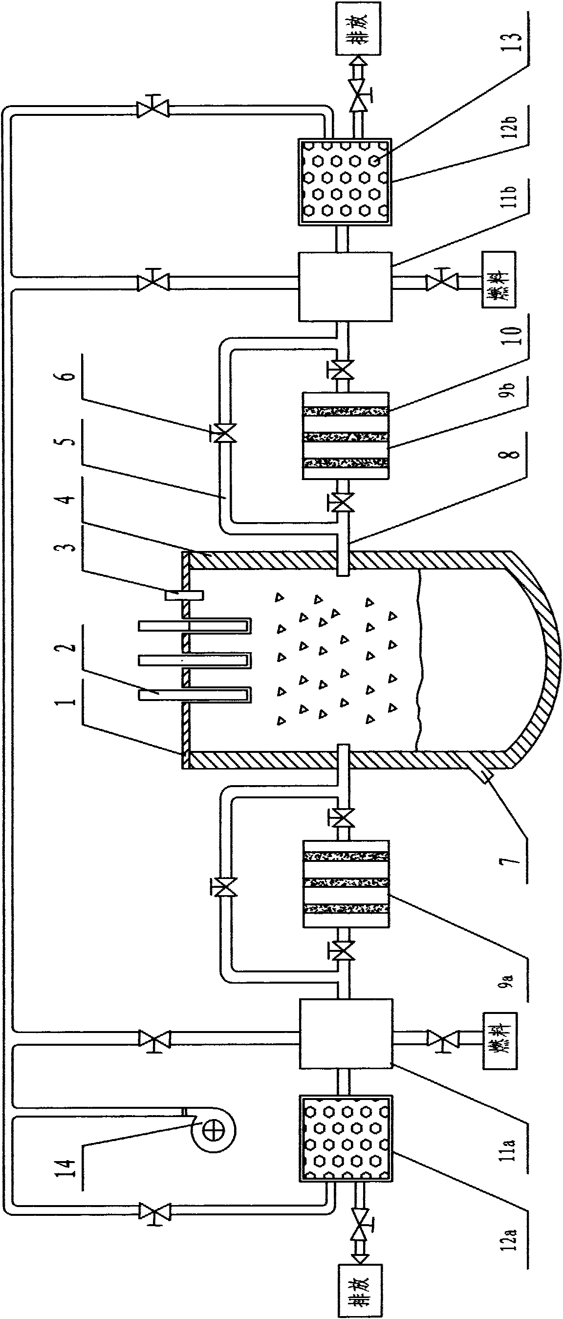
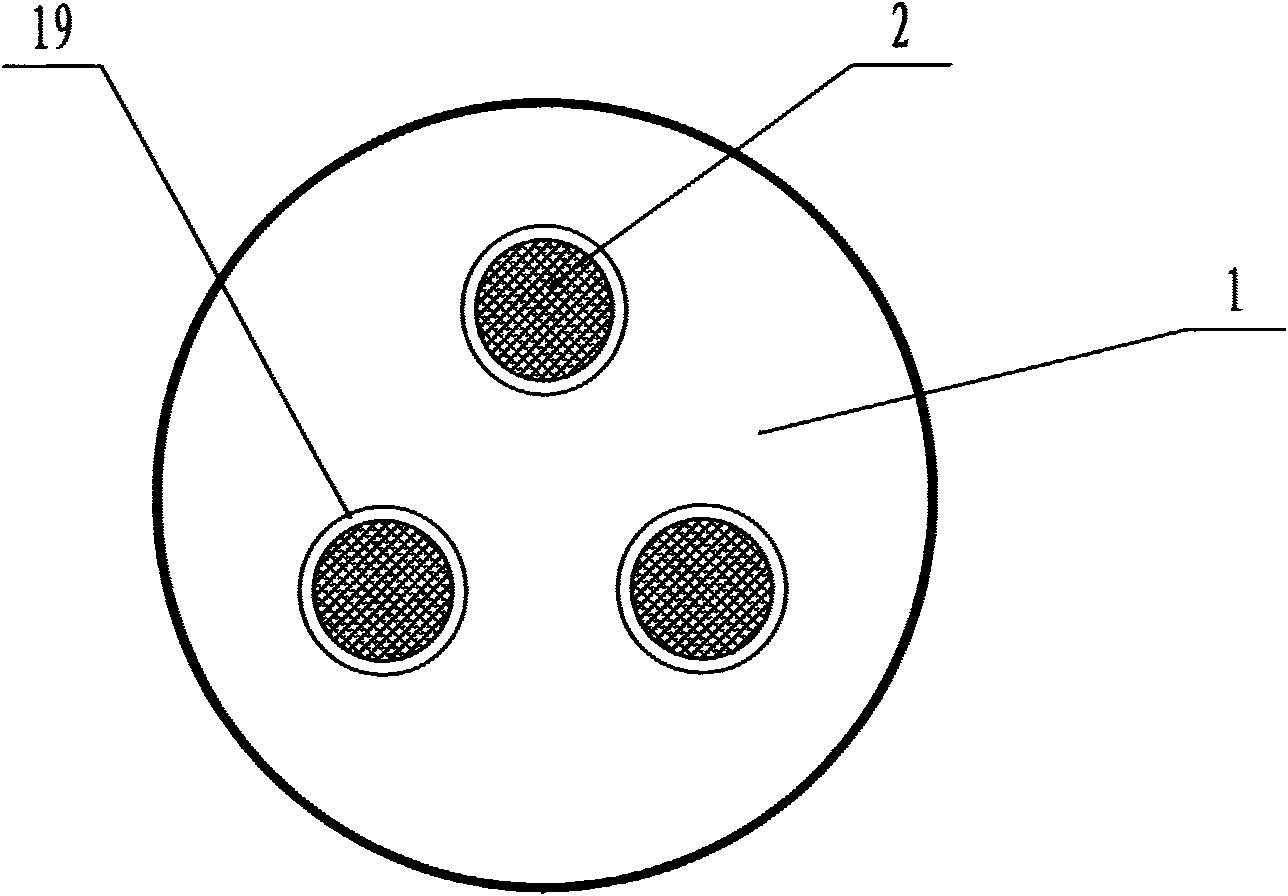
[0024] The regenerative electric arc furnace according to the present invention is as follows figure 1 As shown, it includes a furnace body 4, a furnace cover 1, a feeding device and a discharging device. The lower part of the furnace body 4 has a molten iron outlet 7, such as image 3 As shown, there are three electrode insertion holes 19 on the furnace cover 1, which are respectively inserted into the electrodes 2, and the three electrode insertion holes are distributed in a triangle. Outside the furnace body 4, a pair of combustion chambers 11a, 11b, a pair of heat accumulators 12a, 12b, and a pair of coal gasification tanks 9a, 9b are installed on opposite sides of the furnace body 2. There is a three-layer coal grid 10 in the coal gasification tank. The coal grid is a mesh rectangular structure and is made of wire mesh. The upper part of the coal grid has a coal inlet, and the lower part has a coal ash outlet. The coal inlet and the coal ash outlet are sealed with covers. One end of the coal gasification tank is connected to the furnace body 4 of the electric arc furnace through a connecting pipe 8, and the other end is connected to the combustion chamber. The two ends of the gas tank are connected with bypass 5, and the outlet, inlet and bypass of the gas tank are provided with valves 6. One end of the heat accumulator is connected with the combustion chamber, and the other end is respectively connected with the blower 14 and the exhaust system. The other two paths of the combustion chamber are respectively connected with the combustion air pipeline and the fuel pipeline. The outlet of the blower 14 is divided into four paths, which are respectively connected with two combustion chambers and two heat accumulators, and each path is equipped with a valve 6. The fuel pipeline connected with the combustion chamber and the exhaust gas discharge pipeline connected with the heat accumulator are also equipped with valves. The exhaust system includes a cyclone 15, a bag filter 16, an induced draft fan 17 and a chimney 18. The combustion chamber is provided with a burner, which is a gas fuel burner, and the combustion air and fuel pipelines are connected to the burner. The two combustion chambers alternately burn to produce high-temperature flue gas, and the two heat accumulators alternately store and release heat. The precipitated gas is the gas produced during the reduction of metal iron oxide, which contains a large amount of CO and H 2.
[0025] The heat accumulators 12a, 12b are equipped with a heat storage body 13, and the heat storage body is a ceramic spherical body. The furnace body and furnace cover of the electric arc furnace are of steel structure. The furnace body 4 and the furnace cover 1, and the electrode 2 and the furnace cover 1 are in a sealed connection with a water cooling jacket. The electric arc furnace is equipped with a pressure vent valve 3 as an explosion-proof device. The outer shells of the coal gasification tank 9 and the bypass 5 are lined with refractory insulation materials. The shells of the electric arc furnace body 4 and the furnace cover 1 are lined with refractory insulation materials, and the shells of the combustion chamber, the heat accumulator and the connecting pipelines are lined with refractory insulation materials.
[0026] The working principle of the present invention is that the reduced material is placed in the electric arc furnace body 4, the combustion chamber 11a is started first, and the valves of the fuel passage and the air passage are opened, so that the air and fuel are burned in the combustion chamber to produce high-temperature flue gas Enter the adjacent coal gasification tank 9a, and pass through the three-layer coal grid in the coal gasification tank in turn to make the high-temperature CO in the flue gas 2 It reacts with coal to generate CO. The excess oxygen in the combustion-supporting air is also reduced in the coal gasification tank. The high-temperature reducing gas exiting the coal gasification tank enters the reduction furnace through the connecting pipe 8 and reacts with the materials. During this process, coal gasification The bypass of the box 9a is closed, the valve connected to the coal gasification box 9b on the other side of the reduction furnace is closed, and the corresponding bypass 5 channel is opened. The CO generated during the reduction process enters the combustion chamber 11b, and passes into the combustion chamber 11b through the burner The combustion-supporting air completely combusts the combustible components in the gas from the electric arc furnace. The high-temperature flue gas produced passes through the heat accumulator 12b, transfers the waste heat to the heat accumulator 13, and is discharged from the flue gas pipeline at the end of the accumulator through the cyclone. Separator, bag filter, induced draft fan, chimney discharge into the atmosphere. As the entire equipment works in this way, the temperature of the flue gas out of the heat accumulator gradually rises, and the equipment reverses operation when the flue gas at the outlet of the heat accumulator reaches a specified temperature. The cold air is blown in by the blower 14 and passes through the heat accumulator 12b, where the heat accumulator releases heat to heat the air. The high-temperature air leaving the heat accumulator enters the combustion chamber 11b and mixes and burns with the fuel injected by the burner to produce high-temperature smoke The gas enters the adjacent coal gasification tank 9b and reacts with the coal in the coal grids in the coal gasification tank 9b. The reducing gas exiting 9b enters the electric arc furnace body 4 through the connecting pipe 8 to react. During the process, the bypass of the coal gasification tank 9b is closed, while the outlet and inlet valves of the coal gasification tank 9a on the other side of the electric arc furnace are closed, and the bypass 5 valve 6 is opened, and the gas out of the electric arc furnace enters the combustion through the bypass The chamber 11a is mixed and combusted with the combustion-supporting air entering the combustion chamber. After passing through the heat accumulator 12a, the waste flue gas is transferred to the heat accumulator, and then discharged through the flue gas pipeline at the end of the accumulator, and passed through the cyclone separator, The bag filter, induced draft fan and chimney are discharged into the atmosphere. The reversing operation of the two combustion chambers 11a, 11b, the two heat accumulators 12a, 12b and the two coal gasification tanks 9a, 9b are controlled by setting the temperature of the flue gas outlet of the heat accumulator. When the flue gas from the heat accumulator reaches After the temperature is set, the direction of the air flow is automatically changed, and the combustion chamber on this side is converted from the combustion electric arc furnace to the combustion fuel. The set temperature of the heat accumulator flue gas is 70~150℃, and the specific temperature is set according to the process requirements. The whole process is automatically controlled, and the reversing operation is realized by switching each valve.
[0027] When the material in the arc furnace body reaches a certain temperature and reduction degree, turn off the heat accumulators, combustion chamber and coal gasification box on both sides, insert the electrode 2 on the top of the arc furnace into the furnace, and continue to heat the reduced materials in the arc furnace to complete Melt, open the molten iron outflow port 7 at the bottom of the electric arc furnace, and proceed to the next furnace after the molten iron is completely discharged.

Example Embodiment

[0028] Example 2
[0029] Another embodiment of the present invention is that three sets of regenerative electric arc furnace melting iron-making devices are installed side by side in series to operate. Each device is equipped with two sets of heat storage/coal gasification equipment 23, which are located on opposite sides of the furnace body. Location, the heat storage/coal gasification equipment includes a combustion chamber, a heat accumulator, a coal gasification tank and connecting pipelines. The air supply system, fuel system and exhaust emission system are shared equipment. The operation modes of the electric arc furnace, heat accumulator, combustion chamber, and gas tank of each set of devices are the same as in Example 1. Such as Figure 4 As shown, the furnace bodies 4a, 4b, and 4c of the three sets of electric arc furnaces are connected side by side. The furnace body 4a and the furnace body 4b, and the furnace body 4b and the furnace body 4c are provided with connecting holes 20, and the connecting holes are provided with inserts. The plate valve 21 is connected by pipelines between the furnace bodies 4a and 4c, and a plug-in valve is provided for gas circulation. The three furnace bodies alternately perform heating, reduction and melting processes. When the reduced materials in the furnace body 4a complete the reduction process and melt, the materials in the other two furnace bodies 4b and 4c are heating up and reducing. At this time, the plug-in valve 21 is opened, and the precipitated gas generated in the furnace body 4a enters the furnace bodies 4b, 4c through the connecting hole 20 and pipelines to be used as reducing gas and combustion gas. After the furnace body 4a is melted, when the molten iron and the charging material are discharged through the molten iron outflow port 7, the flap valves on both sides of the furnace body are closed. When the material in the furnace body 4b is melted, the precipitated gas in the furnace body 4b enters the furnace bodies 4a, 4b through the connection holes 20 between the furnace bodies on both sides. Three electric arc furnaces carry out loading and unloading, reduction and melting processes in sequence. The smelting reduction operation process of each device is the same as that of Example 1, and will not be repeated. The purpose of using multiple electric arc furnaces in series operation is to make full use of the precipitated gas generated during the melting process for the reduction process of the reduced materials in the furnace body, so that the precipitated gas during the smelting process can be fully utilized, saving energy, and forming large-scale production. Improve ironmaking production capacity.

Example Embodiment

[0030] Example 3
[0031] Another embodiment of the present invention is as Figure 5 Shown are three electric arc furnaces arranged in a ring shape. The three electric arc furnace bodies 4a, 4b, and 4c are arranged in a triangular shape in a ring shape. Each furnace body is installed close to the other two furnace bodies. A connecting hole and a plug-in valve 21 are provided between each two furnace bodies. Each electric arc furnace is provided with two sets of heat storage/gasification equipment 23, which are located on the two wings of the furnace body, and a set of heat storage/gasification equipment 23 of two adjacent electric arc furnaces are arranged together in a "her" shape. The air supply system, fuel system and exhaust emission system are shared equipment. There is an electrode hanging column 22 in the middle of the three furnace bodies for hanging the electrodes, and the electrodes are inserted between the furnace bodies in turn to carry out the process of melting the reduced iron. The operation mode of this embodiment is the same as that of Embodiment 2. When one of the furnace bodies is melting, the other two are in the heating or reducing process, the flapper valve 21 is opened to allow the precipitated gas to enter the adjacent two furnace bodies. After the melting process is completed, close the insert valve of the furnace body and the adjacent furnace body, discharge the material and load new raw materials, then open the valve and put in the gas for heating and reduction process. With this type of installation, three electric arc furnaces use a set of electrodes. By rotating the electrodes, the electrodes are inserted into the furnace body that needs to enter the melting process in turn. The electrodes can be omitted during heating and reduction to save electrode materials and investment. The ring arrangement is adopted, the equipment is compactly installed, which further saves the space, and further expands the production capacity in the limited space.

PUM

no PUM

Description & Claims & Application Information

We can also present the details of the Description, Claims and Application information to help users get a comprehensive understanding of the technical details of the patent, such as background art, summary of invention, brief description of drawings, description of embodiments, and other original content. On the other hand, users can also determine the specific scope of protection of the technology through the list of claims; as well as understand the changes in the life cycle of the technology with the presentation of the patent timeline. Login to view more.

Similar technology patents

Synthetic catalytic free radical scavengers useful as antioxidants for prevention and therapy of disease

InactiveUS20060149089A1Reduce oxidation ratePrevent oxidationNickel organic compoundsIron organic compoundsMetalCosmetics
Owner:EUKARION

Auxiliary protection gas hood of automatic TIC welder head

ActiveCN103934556AExpand the scope of protectionPrevent oxidationShielding gas supply/evacuation devicesArgon flowEngineering
Owner:HARBIN TURBINE +1

Classification and recommendation of technical efficacy words

  • Prevent oxidation
  • Improve the environment
Why Eureka
Try Eureka