Process for determining particle emission in the exhaust fume stream from an internal combustion engine

A technology of internal combustion engine and exhaust gas flow, applied in the direction of internal combustion piston engine, electronic control of exhaust gas treatment device, diagnosis device of exhaust gas treatment device, etc., can solve problems such as less regeneration cycle, reduce safety margin and reduce additional The effect of fuel consumption

Inactive Publication Date: 2010-02-17
AVL LIST GMBH
View PDF4 Cites 12 Cited by
  • Summary
  • Abstract
  • Description
  • Claims
  • Application Information

AI Technical Summary

Problems solved by technology

This case requires a lower number of regeneration cycles than

Method used


Image

  • Process for determining particle emission in the exhaust fume stream from an internal combustion engine
  • Process for determining particle emission in the exhaust fume stream from an internal combustion engine
  • Process for determining particle emission in the exhaust fume stream from an internal combustion engine

Examples


Embodiment Construction

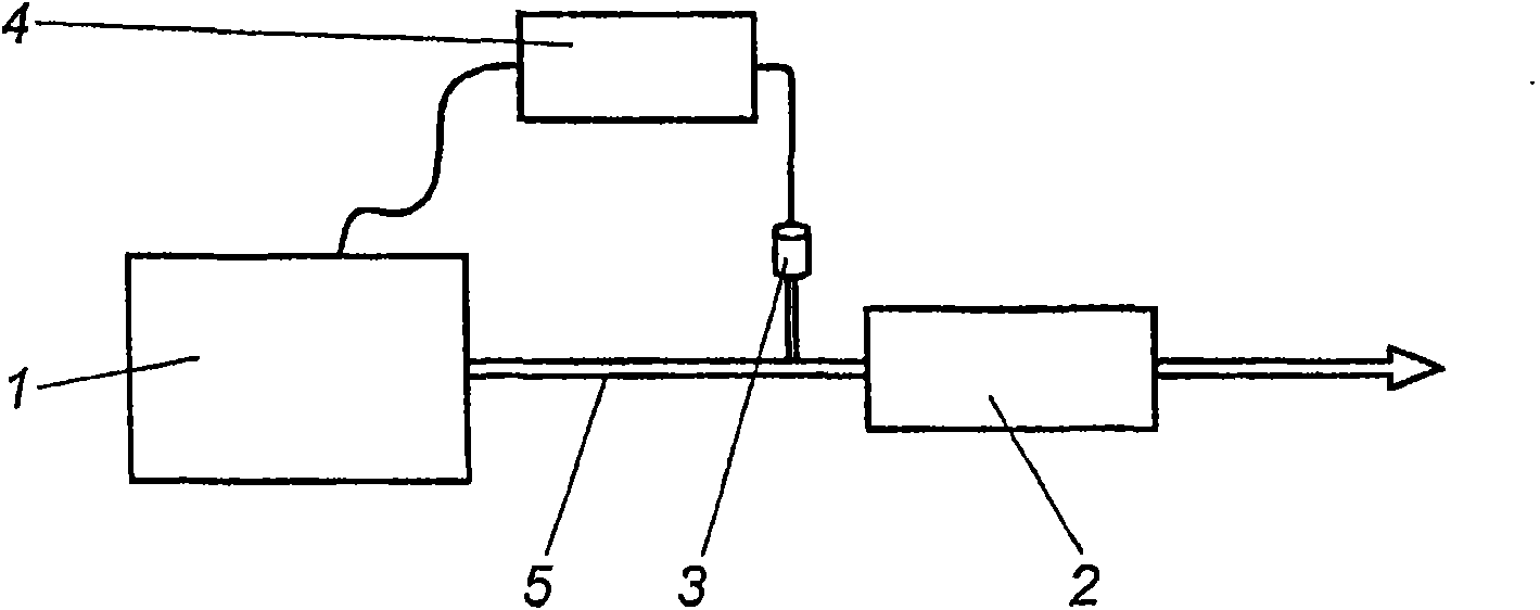
[0069] figure 1 The basic configuration of the system is shown: a particulate filter 2 is arranged in the exhaust tract of an internal combustion engine 1 . A particle sensor 3 is also provided in the exhaust pipe 5 , preferably in front of the particle filter 2 . The internal combustion engine 1 is controlled by an electronic control unit ECU. The particle sensor 2 is also connected to the control unit ECU. There may also be more sensors such as differential pressure sensors, but this is not strictly required for the method of the invention.

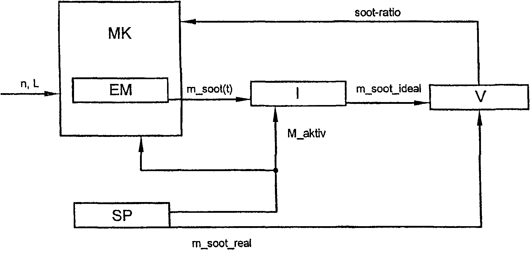
[0070] figure 2 Relevant parts of the control algorithm in the internal combustion engine control unit 4 are shown. From engine operating data such as engine speed n, engine torque M, etc., the conventional emission model EM provides an ideal value m_soot(t) of the particle mass emitted by the engine. Enter this value into integrator I. In addition to the signal input port for the particle mass, the integrator I also has a contro...


PUM


Abstract

A process for determining particle input into a particle filter arranged in the exhaust fume stream of an internal combustion engine makes it possible to determine the mass of deposited particles by taking into account particle and nitrogen oxide emission. The process involves preparing an emission model, measuring the actual particle emissions during a fixed or variable measuring interval, and integrating emissions over this interval; reporting the ideal particle emissions and comparing the actual ones with them; setting a correction factor based on the difference, and taking the correction factor into account in setting the ideal particle emissions.

Description

technical field [0001] The invention relates to a method of determining particulate emissions in the exhaust stream of an internal combustion engine. Furthermore, the invention relates to a method for determining the mass of deposited particles in a particle filter located in the exhaust flow of an internal combustion engine. The invention also relates to a method for controlling the regeneration of an exhaust gas treatment device, in particular a particulate filter, by means of a computer model, preferably based on a characteristic map, wherein the treatment device is divided into at least two, and preferably five, units, and by The deposition model is used to establish the deposition load of each unit, and the regeneration process of the treatment device is started according to the deposition load. Background technique [0002] In order to achieve effective regeneration of the particulate filter, it is necessary to know the sediment load state or the particulate emission ...

Claims


Application Information

Patent Timeline
IPC IPC(8): F02D41/02F01N3/023F01N9/00F01N11/00G01N15/00G01N15/06G01N21/00G01N21/53
CPCF02D41/2451F02D2041/1433G01N15/0656F02D41/1467F01N11/002G01N2015/0046Y02T10/47F02D41/1466F01N11/005Y02T10/40
Inventor H·胡尔瑟M·科睿克勒
Owner AVL LIST GMBH
Why Eureka
Try Eureka