Low-refractive index film, method for forming the low-refractive index film, and antireflection film

A low-refractive-index film and deposition method technology, applied in the field of anti-reflection films, can solve the problems of difficult deposition of anti-reflection films and low-refractive-index films, and achieve the effects of uniform anti-reflection function and good anti-reflection function

Inactive Publication Date: 2010-03-31
SONY CORP
View PDF0 Cites 2 Cited by
  • Summary
  • Abstract
  • Description
  • Claims
  • Application Information

AI Technical Summary

Problems solved by technology

However, even when such a target is used, it is difficult to deposit a low refractive index film suitable for an antireflection film

Method used


Image

  • Low-refractive index film, method for forming the low-refractive index film, and antireflection film
  • Low-refractive index film, method for forming the low-refractive index film, and antireflection film
  • Low-refractive index film, method for forming the low-refractive index film, and antireflection film

Examples


Embodiment 1

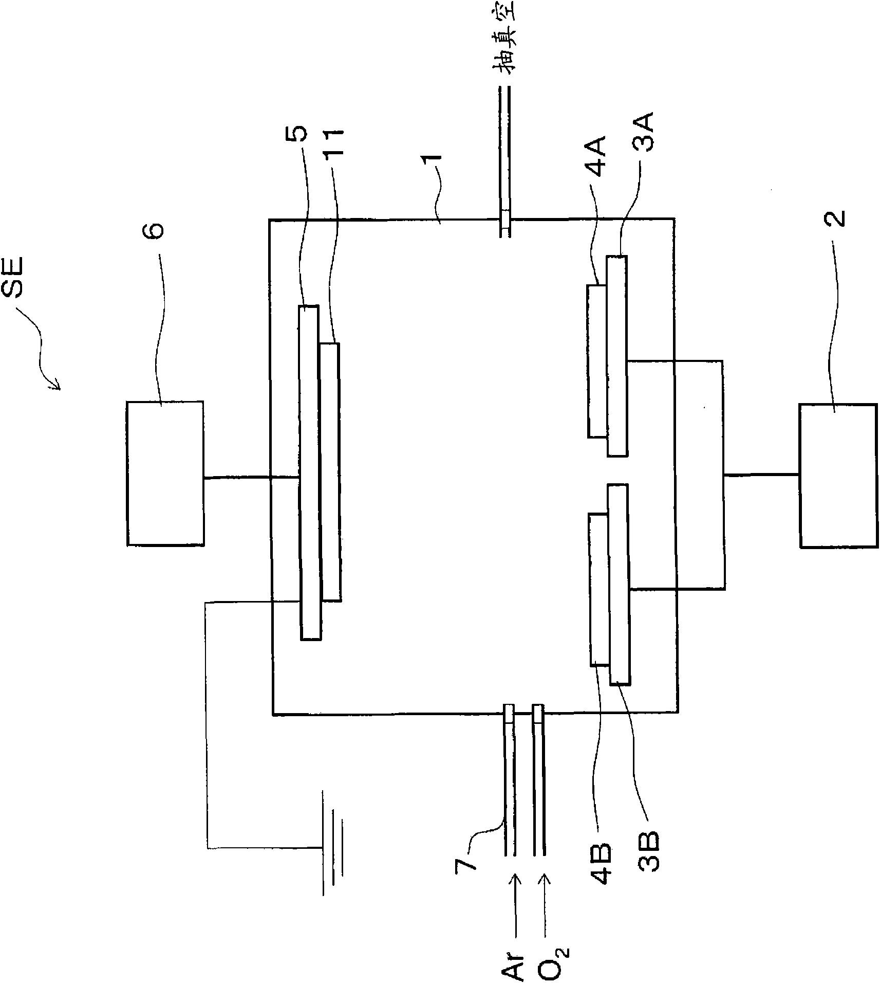
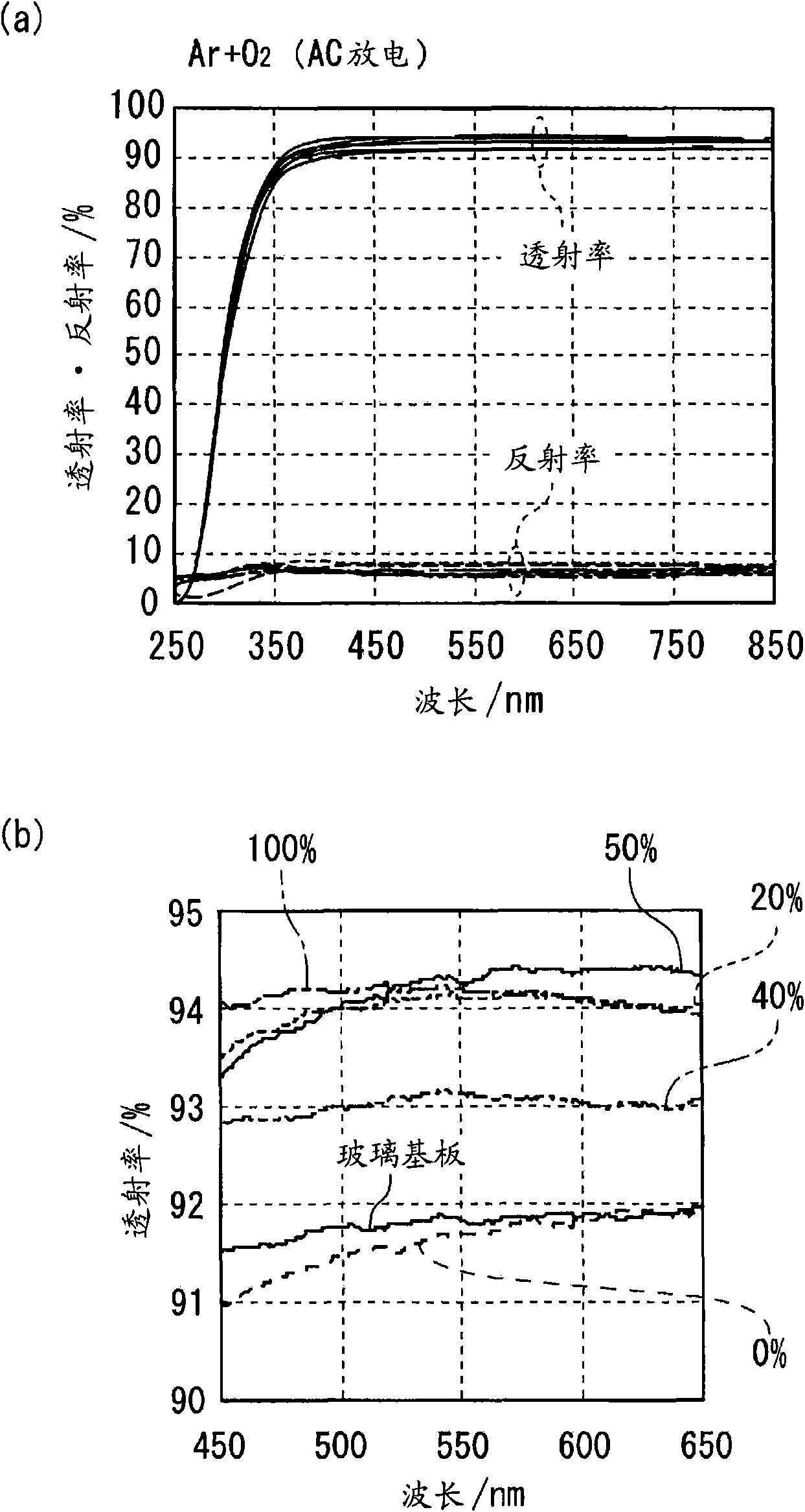
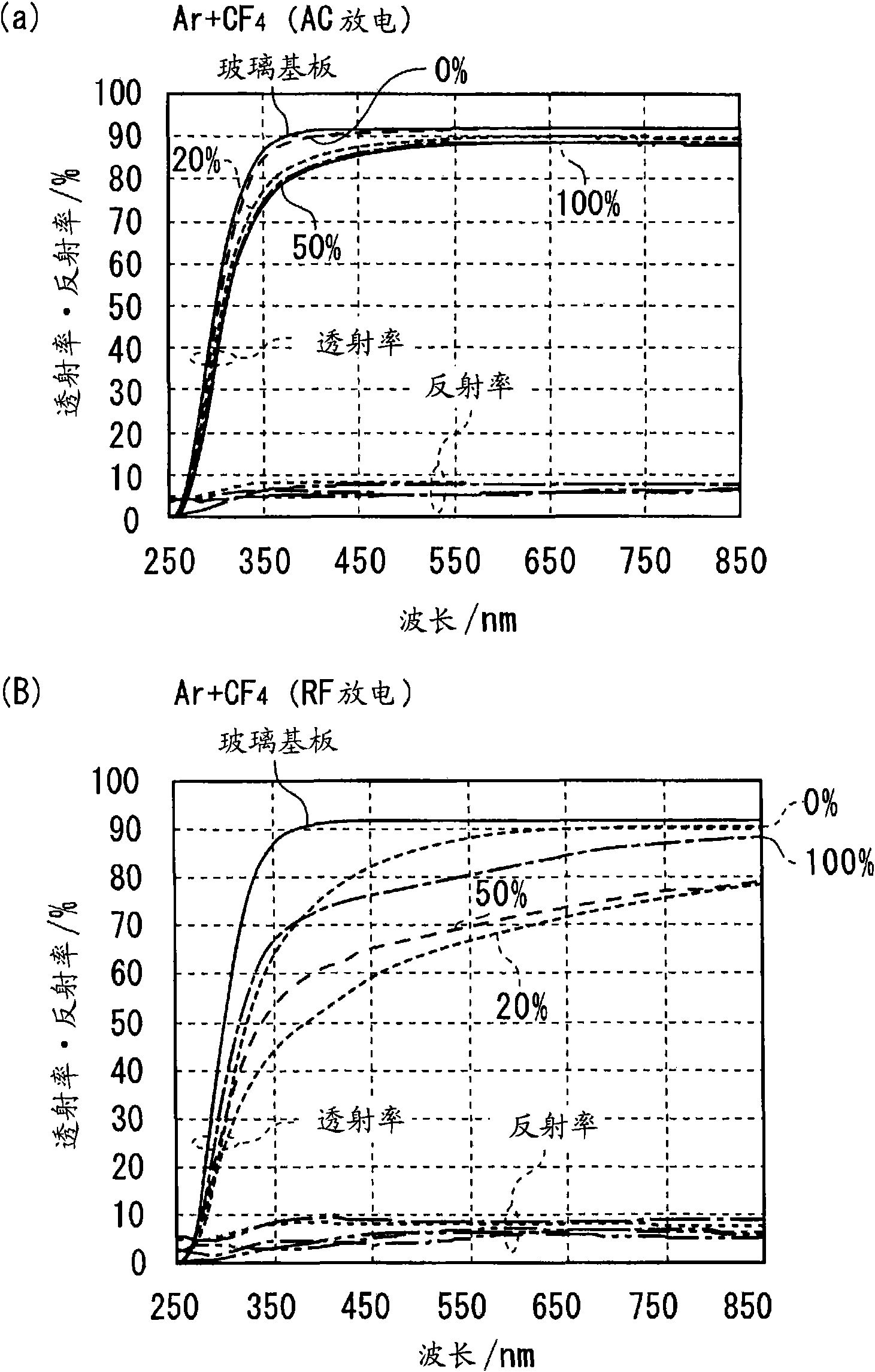
[0040] will be used for figure 1 The reactive sputtering apparatus SE shown, an example of depositing a low-refractive-index film by the method for depositing a low-refractive-index film of the present invention will be described. It should be noted that regarding sputtering conditions, targets 4A and 4B were used: MgF 2 -SiO 2 Sintered body (MgF 2 : SiO 2 =70:30 atomic percent); sputtering gas: Ar; and reaction gas: O 2 As a common condition, and with vacuum chamber 1 inside 5 x 10 -4 Ar gas is introduced at a back pressure below Pa, and pre-sputtering is performed. Subsequently, a low-refractive-index film was prepared under the following deposition conditions. It should be noted that (O 2 Gas flow ratio) = (O 2 gas flow) / {(O 2 Gas flow)+(Ar gas flow)}×100(%).

[0041] (deposition condition)

[0042] Substrate 11: transparent glass substrate

[0043] ·O 2 Gas flow ratio: 0%, 20%, 40%, 50% and 100%

[0044] · Frequency of AC power supply: 90kHz

[0045] ·Suppli...

Embodiment 2

[0097] will be used for figure 1 An example of the deposition of an anti-reflection film is described using the reactive sputtering apparatus SE shown.

[0098] Here, based on the following respective deposition conditions, a film having Figure 4 Anti-reflective coating of the structure shown.

[0099] (1) Substrate: glass substrate

[0100] (2) Adhesive layer: SiO x

[0101] Sputtering target: Boron-doped polysilicon

[0102] · Sputtering gas: Ar

[0103] Reactive gas: O 2

[0104] (3) High refractive index layer a: Nb 2 o 5

[0105] Sputtering target: metal Nb

[0106] · Sputtering gas: Ar

[0107] Reactive gas: CO 2

[0108] ·Film thickness: 25nm

[0109] (4) Low refractive index layer a: MgF 2 -SiO 2

[0110] · Sputtering targets 4A and 4B: MgF 2 -SiO 2 Sintered body (MgF 2 : SiO 2 =70:30 atomic percent)

[0111] · Sputtering gas: Ar

[0112] Reactive gas: O 2

[0113] Deposition conditions: same as those used in the fourth sample of Example 1

...


PUM

PropertyMeasurementUnit
thicknessaaaaaaaaaa
thicknessaaaaaaaaaa
thicknessaaaaaaaaaa

Abstract

This invention provides a method for low-refractive index film formation, which can form a thin film having a uniform composition distribution within the film and a low-refractive index, a low-refractive index film formed by the method for low-refractive index film formation, and an antireflection film using the low-refractive index film. The method for low-refractive index film formation comprises forming a low-refractive index film formed of MgF2-SiO2 on a substrate (11) by reactive sputtering. Targets (4A, 4B) as a sinter of MgF2-SiO2 are provided. An alternating voltage having a frequencyof 20 to 90 kHz is applied across the substrate (11) and the targets (4A, 4B) under a mixed gas atmosphere composed of inert gas and O2 for sputtering deposition.

Description

technical field [0001] The present invention relates to a low-refractive-index film deposited by a reactive sputtering method, a deposition method thereof, and an antireflection film (antireflection film) including the low-refractive-index film. Background technique [0002] Generally, in a display device such as a cathode ray tube (CRT) or a liquid crystal display, an antireflection film is provided on a surface on which an image is displayed. The anti-reflection film is provided to reduce reflection of external light, thereby reproducing preferable image or text information, and is formed by stacking thin film materials having different refractive indices. [0003] Such an anti-reflection film is obtained by, for example, stacking a low-refractive-index layer composed of a low-refractive-index material such as silicon oxide, silicon nitride, or magnesium fluoride on a transparent film base composed of an organic material and a material such as indium oxide containing tin o...

Claims


Application Information

Patent Timeline
Patent Type & Authority Applications(China)
IPC IPC(8): C23C14/34C23C14/06G02B1/11
CPCG02B1/115C23C14/06C23C14/3464C23C14/34G02B1/11
Inventor 竹友干裕河岛利孝大岛宜浩
Owner SONY CORP
Why Eureka
Try Eureka