Universal material testing machine for variable rotating speed pump control hydraulic servo loading system

A material testing machine, hydraulic servo technology, applied in the direction of analyzing materials, servo motors, mechanical equipment, etc., can solve the problem of pollution-sensitive whole machine failure rate and other problems, achieve excellent energy saving effect, reduce the probability of failure, and simplify the hydraulic circuit. Effect

Inactive Publication Date: 2010-04-07
HARBIN INST OF TECH
View PDF0 Cites 21 Cited by
  • Summary
  • Abstract
  • Description
  • Claims
  • Application Information

AI Technical Summary

Problems solved by technology

[0003] The purpose of the present invention is to solve the problem that the electro-hydraulic proportional valve is used as the control mechanism in the existing hydraulic universal material testing machine, and the problem of high failure rate of the whole machine due to the sensitivity of the electro-hydraulic proportional valve to oil pollution is provided. Universal material testing machine with variable speed pump-controlled hydraulic servo loading system

Method used


Image

  • Universal material testing machine for variable rotating speed pump control hydraulic servo loading system
  • Universal material testing machine for variable rotating speed pump control hydraulic servo loading system
  • Universal material testing machine for variable rotating speed pump control hydraulic servo loading system

Examples


specific Embodiment approach 1

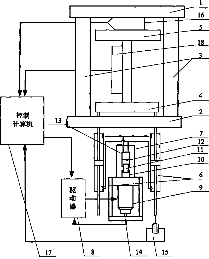
[0010] Specific implementation mode one: the following combination figure 1 and figure 2 Describe this embodiment. This embodiment includes an upper beam 1, a lower beam 2, two columns 3, a workbench 4, a clamping mechanism 5, and an extensometer 18. The two columns 3 form a frame with the upper beam 1 and the lower beam 2. , the frame is supported by the base and bracket of the whole machine, and it also includes two hydraulic cylinders 6, closed oil tank 7, driver 8, motor 9, bidirectional quantitative pump 10, oil replenishment valve 11, bidirectional lock valve 12, two A relief valve 13, an encoder 14, a displacement sensor 15, a pressure sensor 16 and a control computer 17,

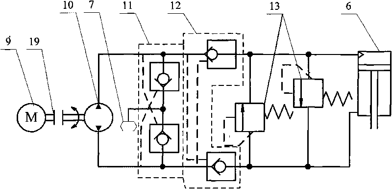
[0011] The power output shaft of the motor 9 is connected to the power input shaft of the two-way quantitative pump 10 through a coupling 19, and the two-way quantitative pump 10 and the two hydraulic cylinders 6 form a closed circuit through two oil circuits, and one end of one oil circuit simult...

specific Embodiment approach 2

[0015] Embodiment 2: The difference between this embodiment and Embodiment 1 is that the oil replenishment valve 11 is composed of two hydraulic control check valves, and the two hydraulic control check valves are connected in parallel between the two oil circuits. The oil inlets of the two hydraulic control check valves communicate with the oil inlets and outlets of the closed oil tank 7 at the same time. Other components and connections are the same as those in Embodiment 1.

[0016] The oil outlets of each of the hydraulic control check valves are respectively connected to different oil passages, and the control oil ports of each hydraulic control check valve are respectively connected to the oil outlets connected to the oil outlets of another hydraulic control check valve. The roads are connected.

[0017] The oil replenishment valve 11 is connected in parallel on the closed circuit and communicated with the closed oil tank 7. Its function is to replenish oil from the clo...

specific Embodiment approach 3

[0018] Embodiment 3: The difference between this embodiment and Embodiment 1 or 2 is that the two-way lock valve 12 is composed of two hydraulically controlled one-way valves. Other compositions and connections are the same as those in the first or second embodiment.

[0019] The oil outlets of the two hydraulically controlled one-way valves described in this embodiment are respectively connected with two different oil ports of the hydraulic cylinder 6, and the oil inlets of the two hydraulically controlled one-way valves are connected with the two-way quantitative pump 10 respectively. Two different oil ports are connected, and the control oil port of each hydraulic control check valve is respectively connected with the oil passage connected with the oil inlet port of the other hydraulic control check valve. The function of the two-way lock valve 12 is to keep the pressure of the hydraulic cylinder 6 in the non-working state, and then prevent the piston rod of the hydraulic c...


PUM


Abstract

The invention relates to a universal material testing machine for a variable rotating speed pump control hydraulic servo loading system, belonging to the field of the material mechanics performance testing equipment, and aiming at solving the problems that the prior hydraulic universal material testing machine which adopts an electro-hydraulic proportional valve as a control system has higher fault rate because the electro-hydraulic proportional valve is sensitive to the oil contamination. The variable rotating speed pump control hydraulic servo loading system is internally arranged below a working platform; a motor is driven by a driver to do rotating movement at variable rotating speed so as to control the pressure and the flow direction of the oil in the outlet of a bidirectional constant flow pump which is connected with the output shaft of the motor and push a hydraulic oil cylinder to do upward loading movement or downward loading movement; the pressure, the displacement and the deformation are transmitted to a control computer by a pressure sensor, a placement sensor and an extensormeter; a control signal is transmitted to the driver by the control computer to realize the closed loop control; and the rotating speed of the motor is transmitted to the driver by a coder to form the inner loop feedback control. The universal material testing machine is used as the metal and nonmetal material mechanics performance testing equipment.

Description

technical field [0001] The invention relates to a universal material testing machine of a variable speed pump-controlled hydraulic servo loading system, which belongs to the field of material mechanical property testing equipment. Background technique [0002] Material testing machine is a kind of equipment suitable for testing and analyzing mechanical properties such as tension, compression, bending, shearing and fatigue of metal and non-metal materials. The overall structure of the existing mainstream hydraulic universal testing machine is as follows: Figure 4 As shown, its hydraulic circuit is as image 3 As shown, this hydraulic universal material testing machine uses an independent pump station as the hydraulic oil source, usually the volume of the independent pump station is 1m 3 Above, this increases the volume of the system, increases the complexity of the system, and increases the cost. At the same time, in order to maintain the pressure required for the system to...

Claims


Application Information

Patent Timeline
Patent Type & Authority Applications(China)
IPC IPC(8): G01N3/00F15B11/16F15B15/18
Inventor 姜继海秦二卫
Owner HARBIN INST OF TECH
Why Eureka
Try Eureka