
Five-bit radio-frequency MEMS phase shifter

A phase shifter and micro-electromechanical technology, which is applied in the field of high frequency band, can solve the problems of difficult electronic communication system supporting use, low number of phase shifters, low phase shift accuracy, etc., and achieves high phase shift accuracy and reliability. Simple processing technology and small step size

Inactive Publication Date: 2010-04-14
UNIV OF ELECTRONIC SCI & TECH OF CHINA
View PDF0 Cites 18 Cited by
  • Summary
  • Abstract
  • Description
  • Claims
  • Application Information

AI Technical Summary

Problems solved by technology

This type of phase shifter is mainly divided into two types: switch linear and distributed. Among them, the switch linear phase shifter uses the MEMS switch to select the signal channel, and uses the transmission line delay to realize the phase shift function. This type of phase shifter is different from the traditional Compared with the phase shifter, although it has the characteristics of low power consumption, high quality factor, high isolation, and compatibility with IC technology, it still has defects such as large size, complex process, and low phase shift accuracy; distributed phase shifters include CPW (Coplanar waveguide) signal line, CPW ground line and the insulating layer on the surface of the signal line, MEMS metal beam and its support, proportional capacitor upper plate, lower plate, 2-4 DC loading electrodes and MEMS metal The connecting wires between the beams, the substrate and the insulating layer on it; its working principle is to periodically load the driving voltage on the MEMS beam, and use the phase shifting characteristics of the capacitor to realize the phase shifting function; the distributed phase shifting Although the device has the characteristics of relatively simple structure and small volume, because its metal beam adopts plate beam and fixed support structure, the change of the distance between the beam and the corresponding signal line is realized by the deformation of the metal beam, while the plate body The elastic coefficient of the metal beam is large, so the required pull-down voltage is high (20V ~ 80V), the phase shift step is also large, the number of phase shifters is still low (only 2-4), and the phase shifting accuracy is poor , it is difficult to be used with the existing electronic communication system; and to achieve small-step phase shifting and increase the number of phase shifters, it is necessary to increase the width of the metal beam and increase its capacitance ratio, that is, to increase its volume , which is not conducive to its miniaturization; its DC bias voltage is directly loaded on the MEMS metal beam through the positive pole of the DC loading electrode and the connection line, and the negative pole is connected to the CPW signal line, so there are both DC and DC voltage on the MEMS metal beam. AC signal, the MEMS metal beam will lose the phase shifting function due to the self-excited oscillation caused by AC and DC crosstalk; in addition, in order to achieve a high capacitance ratio, the phase shifter needs to set the distance between the upper and lower plates of the proportional (compensation) capacitor relatively The near and upper plates and the metal beams cannot be located on the same horizontal plane, and the upper plate needs to be manufactured by electroplating alone, which increases the complexity of the production; therefore, the distributed phase shifter has a high pull-down voltage. , large phase shift step, low phase shift number and phase shift accuracy, and poor reliability, it is difficult to be used with existing electronic communication systems, and does not meet the requirements of the development of modern wireless communication systems.

Method used


Image

  • Five-bit radio-frequency MEMS phase shifter
  • Five-bit radio-frequency MEMS phase shifter
  • Five-bit radio-frequency MEMS phase shifter

Examples


Embodiment Construction

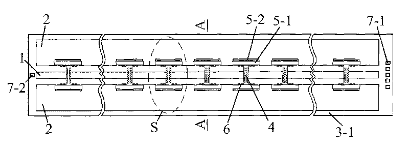
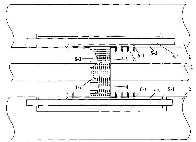
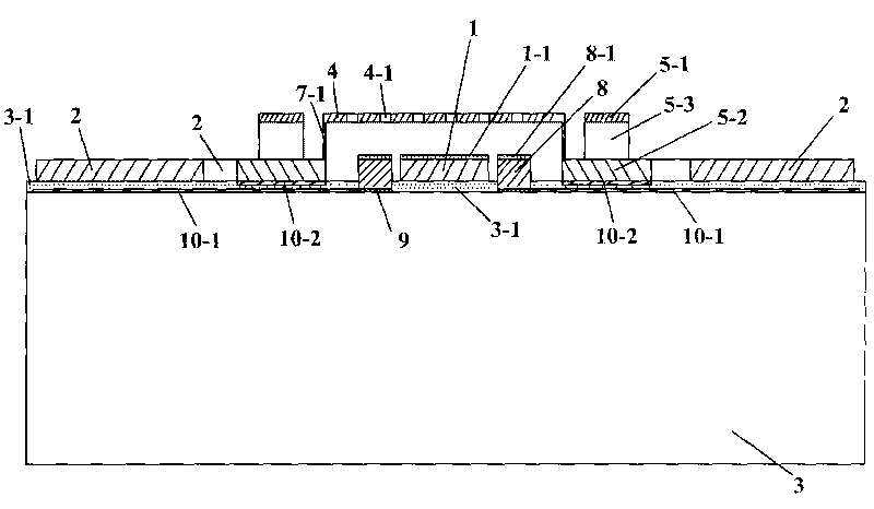
[0012] Take a five-bit RF MEMS phase shifter with a frequency of 10GHz (X-band) as an example: CPW signal line 1 (length×width×thickness) is 5.7cm×100μm×2μm, and the insulating layer 1-1 on it is 0.35mm thick. μm of silicon dioxide (SiO 2 ), two CPW ground wires 2 (length×width×thickness) 5.7cm×400μm×2μm, the distance between the inner sides of the two ends of the two ground wires and the signal line 1 is 107μm, and the grooves (length×depth) in the middle of the two ground wires are 400μm×103μm; in order to meet the requirement of 10GHz working frequency, the MEMS metal beam 4 (length×width×thickness) is 320×94×1.0μm, and the hole 4-1 on it is processed by wet etching, and the diameter of each hole is Φ5 μm, the horizontal center distance of each hole is 9 μm, the longitudinal center distance is 7 μm, the corresponding side distances are 4 μm and 2.5 μm respectively, the initial gap between the lower surface of the metal beam 4 and the upper surface of the insulating layer 1-...


PUM

PropertyMeasurementUnit
Apertureaaaaaaaaaa
Center distanceaaaaaaaaaa

Abstract

The invention belongs to a five-bit radio-frequency MEMS phase shifter in radio-frequency communication and MEMS technologies, comprising a CPW signal wire, an insulating layer, a grounding wire, an MEMS hole-plate metal beam, an elastic cantilever-type support, a proportional capacitor, a direct current (DC) bias electrode, an insulating layer, 31 MEMS switches consisting of bias leads, 5 DC loaded electrodes, connecting leads and a substrate with an insulating layer. The invention effectively overcomes the defect of phase-shifting malfunction of the MEMS metal beam due to self oscillation by adding the DC bias electrode, adopts the hole-plate metal beam and the elastic cantilever-type support to decrease a voltage to be pulled down by approximate 9V, not only realizes the small step of 11.25, 5-bit phase shifting and 32 phase-shifting states, but also has little reflection loss and high phase-shifting precision up to 3.5 and has the advantages of low insertion loss and pull-down voltage, small step amplitude, high bits, phase-shifting precision and reliability of the phase shifter, simpler machining process, matched use with a modern electronic communication system, and the like.

Description

technical field [0001] The invention belongs to radio frequency communication and microelectromechanical (MEMS) technology, in particular to a five-bit distributed radio frequency microelectromechanical structure phase shifter, which is especially suitable for high frequency bands such as radio frequency / microwave. Background technique [0002] Phase shifters are the basic components of communication system equipment, and microwave and millimeter wave phase shifters are key components of receiver transmitters and phased array antennas. At present, traditional phase shifters are mainly realized by ferrite materials, PIN diodes or FET switches, which are large in size and high in power consumption, making it difficult to adapt to the development requirements of modern wireless communication systems. In recent years, the rapid development of microelectromechanical systems (MEMS) technology has promoted the development of radio frequency microelectromechanical (RF MEMS) phase sh...

Claims


Application Information

Patent Timeline
IPC IPC(8): H01P1/18B81B7/02
Inventor 鲍景富张晓升杜亦佳
Owner UNIV OF ELECTRONIC SCI & TECH OF CHINA
Learn More