Supercharge Your Innovation With Domain-Expert AI Agents!

Imaging system for wide dynamic range based on optical grating and CCD imaging detector

An imaging detector, wide dynamic range technology, applied in the field of light intensity detection system, can solve the problems of unfavorable optical path integration and further expansion of dynamic range, high development and production cost, difficulty in short pulse light detection, etc. Dynamic detection range, extended dynamic range, the effect of a wide range of applications

Inactive Publication Date: 2011-08-24
INST OF OPTICS & ELECTRONICS - CHINESE ACAD OF SCI
View PDF9 Cites 0 Cited by
  • Summary
  • Abstract
  • Description
  • Claims
  • Application Information

AI Technical Summary

Problems solved by technology

[0004] There are many researches on multiple exposure technology in China. For example, Chinese patent application numbers are 200810021158 and 200480018951.6. Expose before collecting CCD data to obtain light intensity distribution in different areas, and then divide the CCD target surface into several areas with different exposure times. , perform the second exposure and collect the output image, this method does not need to modify the circuit of the CCD detector itself, but several exposures are required before the last exposure to determine the exposure time of different areas
[0005] Chinese patent 200610053328 introduces a method of splitting interference spectrum signals by using a spectroscopic plate with a higher splitting ratio. This method is similar to the method proposed in this patent and does not require multiple exposures, but using a spectroscopic plate is not conducive to the optical path itself. The integration and further extension of the dynamic range
[0009] U.S. patents US4623928, US4873561, US5235197, US6008486, US6040570, US6501504, etc. all achieve a high dynamic range by changing the internal circuit structure of the CCD. The above-mentioned patents acquire multiple times through the internal circuit of the CCD or by setting the threshold, or control the integration time, or The method of performing multiple exposures or double-threshold integration improves the final output dynamic range of the CCD; however, as emphasized above, these methods must go deep into the internal circuit structure of the CCD, which will inevitably bring high development and production costs. , and complex manufacturing process, and no matter what form of improvement method, it is difficult to detect fast-changing light beams, especially short pulse light, by controlling the integration time, by multiple exposures, and by setting the threshold. is undetectable

Method used


Image

  • Imaging system for wide dynamic range based on optical grating and CCD imaging detector
  • Imaging system for wide dynamic range based on optical grating and CCD imaging detector
  • Imaging system for wide dynamic range based on optical grating and CCD imaging detector

Examples


Embodiment Construction

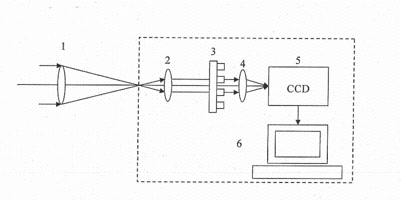
[0023] Such as figure 1As shown, the present invention includes: a front matching lens 2, a grating 3, a rear matching lens 4, a CCD imaging detector 5, and a computer system 6, wherein the front matching lens 2 mainly converts the converging incident light beam into parallel light so as to facilitate the introduction Modulation of the grating, the rear matching lens 4 is used to image the incident light beam as the imaging lens 1; the imaging light beam converges at the entrance of the wide dynamic range imaging system based on the grating and CCD imaging detector through the imaging lens 1, and the converged light beam passes through The front matching lens 2 outputs parallel light beams, and the grating 3 modulates the phase or light intensity of the output parallel light beams. The parallel light beams modulated by the grating are transmitted over a short distance or directly enter the rear matching lens 4, and output multiple Light beams of different sizes converge on di...


PUM


Abstract

The invention discloses an imaging system for a wide dynamic range based on an optical grating and a CCD imaging detector, which consists of the optical grating, a matching lens, the CCD imaging detector and a computer, and is characterized in that an imaging beam is focused by an imaging lens, the beam enters a first matching lens after passing through a focal plane and outputs a parallel beam, and the parallel beam passes through the optical grating and enters a second matching lens to image on the CCD imaging detector. The optical grating can divide a light spot originally imaged on the CCD imaging detector into a plurality of light spots with unequal sizes of light intensity, the plurality of light spots with the unequal sizes of light intensity can be combined through simple operation, and the dynamic range and a signal-to-noise ratio of the original CCD probe is greatly improved.

Description

technical field [0001] The invention relates to a light intensity detection system, in particular to a wide dynamic range imaging system based on a grating and a CCD imaging detector. Background technique [0002] At present, in many application fields, CCD imaging detectors are used to capture targets and analyze the structural characteristics of targets. CCD imaging detectors are also used in many optical systems, especially coherent optical systems, J.R.Fienup, in the article "Phase retrieval algorithms: a comparison" APPLIED OPTICS, Vol.21, No.15, 1982, clearly pointed out that through Accurately measure the near-field and far-field light intensity distribution, and the corresponding iterative algorithm can accurately reverse the aberration contained in the incident beam; The spot information at , without a wavefront detector, the adaptive optics system can correct the phase distortion contained in the incident light. [0003] However, the current general CCD imaging d...

Claims


Application Information

Patent Timeline
IPC IPC(8): G01J1/00G01J1/04
Inventor 黄林海饶长辉
Owner INST OF OPTICS & ELECTRONICS - CHINESE ACAD OF SCI
Features
  • R&D
  • Intellectual Property
  • Life Sciences
  • Materials
  • Tech Scout
  • Unparalleled Data Quality
  • Higher Quality Content
  • 60% Fewer Hallucinations
Learn More