Aluminium electrolysis bath

An aluminum electrolytic cell and electrolytic cell technology, which is applied in the field of aluminum electrolytic cells, can solve the problems of low energy utilization rate, large floor space, and short service life, and achieve the effects of high energy utilization rate, small floor space and long service life.

Active Publication Date: 2010-05-19
GUIZHOU BRANCH CHINA ALUMINUM IND
View PDF11 Cites 20 Cited by
  • Summary
  • Abstract
  • Description
  • Claims
  • Application Information

AI Technical Summary

Problems solved by technology

[0015] The purpose of the present invention is to provide an aluminum electrolytic cell that can effectively overcome the problems of the traditional aluminum electrolytic cell such as short life, large floor space, low energy utilization rate, and large pollution.

Method used


Image

  • Aluminium electrolysis bath
  • Aluminium electrolysis bath
  • Aluminium electrolysis bath

Examples


Embodiment 1

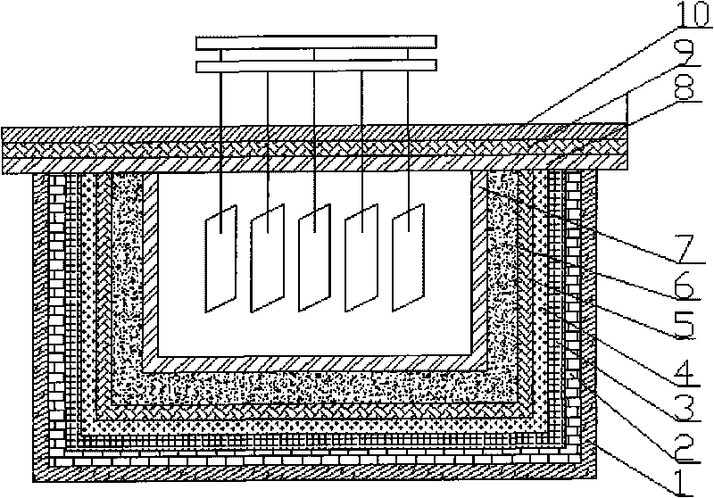
[0045] An aluminum electrolytic cell, the structure of the horizontal cell bottom and the vertical side cell wall of the electrolytic cell sequentially includes: a calcium silicate board layer 1, a light insulation brick layer 2, a refractory brick 3, an anti-seepage material layer 4, silicon Alumina fiber paper layer 5, alumina layer 6, silicon carbide brick or corundum brick or high alumina ceramic brick layer 7; aluminum electrolytic cell cover plate structure consists of corundum plate or high alumina ceramic plate or silicon carbide plate layer from bottom to top 8. Aluminum silicate fiber board layer 9. High alumina cement prefabricated board layer 10. see figure 1 .

Embodiment 2

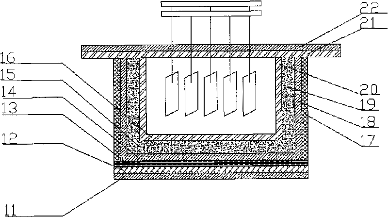
[0047] An aluminum electrolytic cell, the structural composition of the horizontal cell bottom of the electrolytic cell sequentially includes a calcium silicate board layer 11, an insulating brick layer 12, an anti-seepage material layer 13, a calcium silicate fiber paper layer 14, and an aluminum oxide layer 15 from outside to inside and high-alumina ceramic brick layer 16; the structure of the vertical side tank wall includes refractory brick layer 17, aluminum silicate fiber paper layer 18, alumina layer 19 and high-alumina ceramic plate layer 20 from outside to inside; aluminum electrolytic cell cover plate The structural composition includes a corundum plate layer 21 at the bottom layer and an aluminum silicate fiber plate layer 22 compounded with the corundum plate layer. see figure 2 .

Embodiment 3

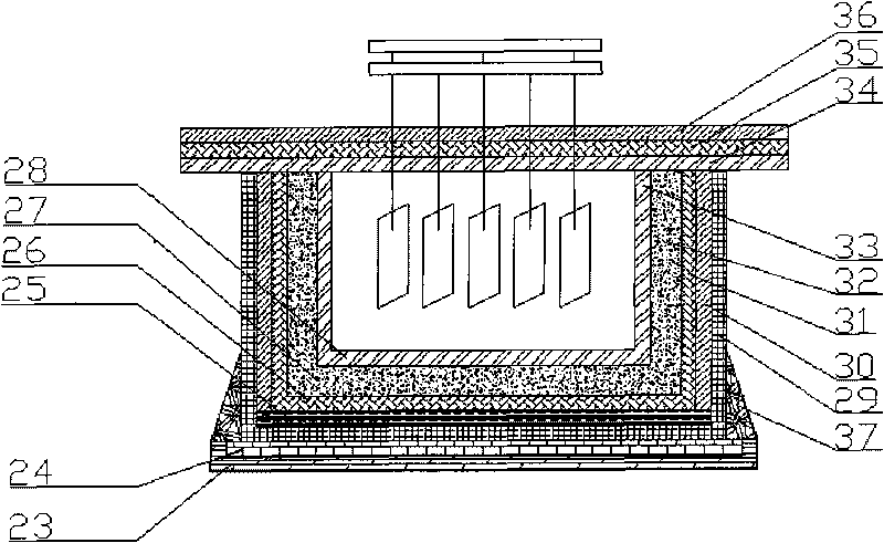
[0049] An aluminum electrolytic cell, the structure of the horizontal cell bottom of the electrolytic cell includes a calcium silicate board layer 23, an insulating brick layer 24, an anti-seepage material layer 25, a calcium silicate fiber paper layer 26, and an aluminum oxide layer 27 from outside to inside. and silicon carbide brick layer 28; the structure of the vertical side groove wall includes refractory brick layer 29, aluminum silicate fiber paper layer 30, high alumina ceramic plate layer 31, aluminum oxide layer 32 and silicon carbide-silicon nitride The plate layer 33; the structure of the cover plate of the aluminum electrolytic cell consists of high alumina ceramic plate layer 34, high alumina cement prefabricated plate layer 35 and aluminum silicate fiber plate layer 36 from bottom to top; Cement castable angular reinforcement 37 . see image 3 .


PUM

PropertyMeasurementUnit
thicknessaaaaaaaaaa
thicknessaaaaaaaaaa
thicknessaaaaaaaaaa

Abstract

The invention relates to an aluminium electrolysis bath used in primary aluminium production. The aluminium electrolysis bath is characterized in that the electrolysis bath comprises an aluminium electrolysis bath body and an aluminium electrolysis bath cover plate, wherein the bath body comprises a horizontal bath bottom and vertical side bath walls connected with the bath body into a whole; and the cover plate is a horizontal cover plate which covers the upper ends of the vertical bath walls and is provided with an electrode through hole. The aluminium electrolysis bath has the advantages of ideal airtightness of bath body structure, high energy utilization rate, no pollution, small land occupation and high capacity per unit area, scientifically realizes heat preservation in a melt zone and the upper part of the electrolysis bath, and has a long service life.

Description

technical field [0001] An aluminum electrolytic cell relates to an aluminum electrolytic cell used for primary aluminum production. Background technique [0002] The bottom surface and side structure of the traditional aluminum electrolytic cell lining are different. The bottom surface is generally laid with calcium silicate boards, lightweight insulation bricks, refractory bricks, anti-seepage materials, and cathode carbon blocks. block or silicon carbide-carbon composite block, the cathode paste is rammed at the joint between the side and the bottom; the cathode and the anode are horizontally opposite, and the electrolyte and aluminum liquid are distributed in horizontal layers between the cathode and the anode. [0003] US 5149412 discloses a production process of an aluminum electrolytic cell liner and its refractory material. The electrolytic cell liner includes a metal tank shell, a closed side liner, a bottom liner and a refractory liner, and at least one layer of ref...

Claims


Application Information

Patent Timeline
Patent Type & Authority Applications(China)
IPC IPC(8): C25C3/08
Inventor 杨建红李旺兴陈喜平
Owner GUIZHOU BRANCH CHINA ALUMINUM IND
Why Eureka
Try Eureka