
Shield cutter rotary drive pressure adapting hydraulic control system of proportional valve controlled energy accumulator

A technology of hydraulic control system and shield cutter head, which is applied in mining equipment, earthwork drilling, tunnels, etc., and can solve problems such as reduced efficiency of the pressure oil system, increased temperature, and difficult maintenance, so as to improve efficiency and reliability , avoid overflow loss and keep the system clean

Inactive Publication Date: 2010-06-02
CENT SOUTH UNIV
View PDF0 Cites 8 Cited by
  • Summary
  • Abstract
  • Description
  • Claims
  • Application Information

AI Technical Summary

Problems solved by technology

However, the closed system also has the disadvantages that it is not easy to dissipate heat, system pollution is not easy to discharge, and maintenance is difficult.
Especially in the face of complex stratum environment, the cutter head is usually subjected to a large impact during the process of starting, running, braking, and even the cutter head is stuck, and the system cannot adapt to this severe impact. The solution is to use the overflow of the relief valve for safety protection, which will not completely avoid the impact, but will also lead to excessive overflow of pressure oil, which will reduce the system efficiency and increase the temperature, resulting in a change in the working environment of the hydraulic system. Worse, the cost and difficulty of maintenance will increase, and in extreme cases, the tool or damage will be caused by frequent impacts for a long time or the untimely response of the relief valve

Method used


Image

  • Shield cutter rotary drive pressure adapting hydraulic control system of proportional valve controlled energy accumulator
  • Shield cutter rotary drive pressure adapting hydraulic control system of proportional valve controlled energy accumulator

Examples


Embodiment Construction

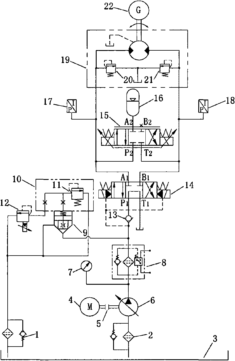
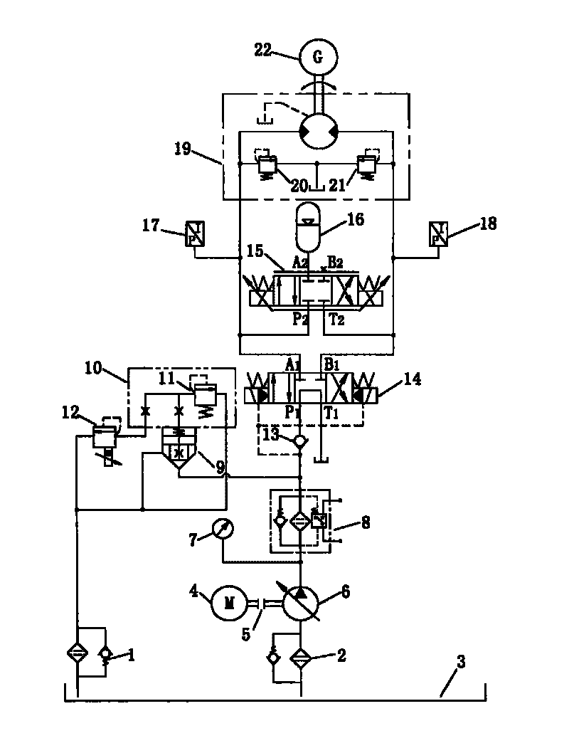
[0016] Such as figure 1 As shown, the motor 4 in the main circuit of the present invention is connected with the constant power variable pump 6 through the coupling 5; the oil suction port of the constant power variable pump 6 is connected to the oil outlet of the oil suction filter 2, and the oil outlet is connected in parallel with the pressure gauge 7 is connected with the inlet of high-pressure oil filter 8; the oil outlet of high-pressure oil filter 8 is connected with the oil inlet of cartridge valve 9 in parallel and then connected with the oil inlet of check valve 13; proportional relief valve 12 and control cover 10 The oil inlet of the built-in safety valve 11 is connected to the control oil port of the cartridge valve 9 through the control cover plate 10; 1; the P1 port of the electro-hydraulic reversing valve 14 is connected with the oil outlet of the one-way valve 13; the T1 port is connected with the oil tank 3; 17. The oil inlet of the first relief valve 20 is ...


PUM


Abstract

The invention discloses a shield cutter rotary drive pressure adapting hydraulic control system of a proportional valve controlled energy accumulator. The system comprises a main hydraulic loop and a pressure adapting loop, wherein the main hydraulic loop consists of a motor, a constant power variable pump, a cartridge valve, a control cover plate, a proportional overflow valve, a one-way valve, an electro-hydraulic reversing valve, a proportional reversing valve, an energy accumulator, a quantitative motor and a speed reducer. The system judges the load characteristic when a cutter cuts a rock mass by detecting the system pressure through a pressure sensor, adjusts the proportional reversing valve according to the preset fuzzy adaptive PID control strategy and the change of a pressure signal, reasonably controls the opening direction, size and duration of the energy accumulator to absorb the load impact under different working conditions, and stores the impact energy reutilized for driving the cutter so as to effectively control the influences of system cavity enlargement and rigidity reduction because the energy accumulator is connected. By adopting the proportional valve controlled energy accumulator, the system can adapt the load impact caused by the complex stratum better, and has better energy conservation and reliability.

Description

technical field [0001] The invention relates to a fluid pressure actuator, in particular to a proportional valve-controlled energy accumulator shield cutter head rotary drive pressure adaptive hydraulic control system. Background technique [0002] Shield tunneling is a complete set of modern tunnel construction equipment integrating machinery, electricity, hydraulic pressure, sensing and information technology. It has the characteristics of high efficiency, speed, high quality and safety. Especially in the construction of long tunnels and urban underground tunnels, it has good adaptability to the comprehensive influence of factors such as construction conditions, construction period, and construction safety. With less impact, excavation tasks can be completed more safely, quickly and efficiently. [0003] The shield cutter head rotary drive system is the core component of the shield machine. It is used to provide the appropriate speed and torque for the cutter head during ...

Claims


Application Information

Patent Timeline
IPC IPC(8): E21D9/093F15B1/02
Inventor 夏毅敏滕韬罗德志周喜温张魁
Owner CENT SOUTH UNIV
Learn More