Method for manufacturing combined cam shaft

A manufacturing method and camshaft technology, applied in the field of mechanical processing, can solve the problems of complex mold processing, demanding process requirements, and high manufacturing costs, and achieve the effects of low overall cost, simple overall process, and material saving

Inactive Publication Date: 2010-06-16
CENT IRON & STEEL RES INST
View PDF3 Cites 15 Cited by
  • Summary
  • Abstract
  • Description
  • Claims
  • Application Information

AI Technical Summary

Problems solved by technology

[0009] The present invention solves the problem that the present knurling method has harsh process requirements, low efficiency, high manufacturing cost, expensive equipment required by the internal high-pressure forming method, complex mold processing, high cost, and the fact that the hollow tube is used as the main shaft. In order to solve the problems such as large errors in parts positioning and customized tooling, a method for assembling and connecting combined camshafts is provided.

Method used


Image

  • Method for manufacturing combined cam shaft
  • Method for manufacturing combined cam shaft
  • Method for manufacturing combined cam shaft

Examples


Embodiment 1

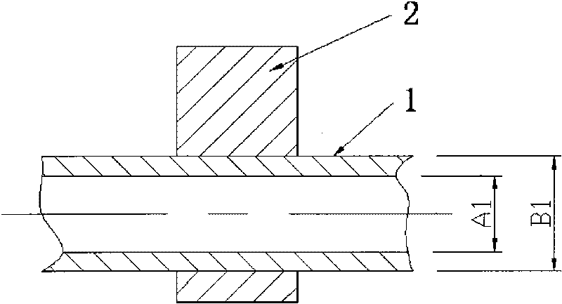
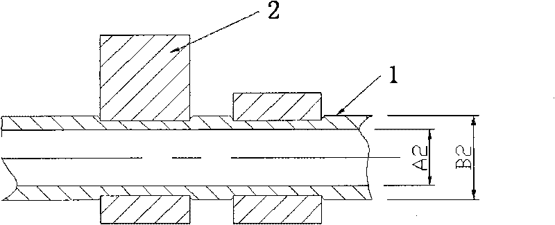
[0026] The mandrel is 20# steel pipe, inner diameter A1=16.00mm, outer diameter B1=22.02mm; the cam is an iron-based powder metallurgy part, its hardened layer thickness is greater than 1.50mm, HRC hardness is 55, inner diameter C=20.05mm; tapered slider Middle outer diameter D=16.20mm. The numerical control assembly machine is used to carry out interference tight fit and cold fit positioning according to the specified sequence, axial distance and phase angle requirements, and the cam 2 is fixed on the mandrel 1 through tight fit and cold fit, and then the tapered slider 3 is pulled by hydraulic pressure. Mandrel 1 is used to make the mandrel plastically deformed, so as to be closely combined with the elastically deformed cam 2. After expanding the tube, the inner diameter of the mandrel becomes A2=16.18mm, the outer diameter of the joint between the mandrel and the cam remains unchanged, and the outer diameter of the joint between the mandrel and the cam becomes B2=22.16mm. ...

Embodiment 2

[0028] The mandrel is 45# steel pipe, inner diameter A1=18.50mm, outer diameter B1=23.51mm; the cam is an iron-based powder metallurgy part, its hardened layer thickness is greater than 1.85mm, HRC hardness is 59, inner diameter C=23.55mm; tapered slider Middle outer diameter D=18.65mm. The numerical control assembly machine is used to carry out interference tight fit and cold fit positioning according to the specified sequence, axial distance and phase angle requirements, and the cam 2 is fixed on the mandrel 1 through tight fit and cold fit, and then the tapered slider 3 is pulled by hydraulic pressure. Mandrel 1 is used to make the mandrel plastically deformed, so as to be closely combined with the elastically deformed cam 2. After expanding the tube, the inner diameter of the mandrel becomes A2=18.62mm, the outer diameter of the joint between the mandrel and the cam does not change, but the outer diameter of the joint between the mandrel and the cam changes to B2=23.61mm. ...


PUM

PropertyMeasurementUnit
depthaaaaaaaaaa
thicknessaaaaaaaaaa
thicknessaaaaaaaaaa

Abstract

The invention belongs to the technical field of machining, and relates to a method for manufacturing a combined cam shaft, in particular to the method for manufacturing the combined cam shaft with a hollow tube mandrel. The method comprises the following manufacturing processing steps: firstly, straightening the hollow tube mandrel; secondly, performing tight fit and cold assembled positioning on a cam, a shaft neck component and a mandrel by using a numerical controlled assembling machine, and then realizing close connection of the cam, a shaft neck and the mandrel by machining expanding, so that the mandrel which generates plastic deformation is firmly combined with the cam and the shaft neck which generate elastic deformation; and finally, fixing drive components at the two ends of the cam shaft by a laser welding method. The method for manufacturing the combined cam shaft has the advantages of simple overall process, obviously reduced weight compared with a cast iron cam shaft, low integrated cost and high assembly precision, and completely meets the using requirements on the cam shafts of various automobile engines.

Description

Technical field: [0001] The invention belongs to the technical field of mechanical processing, and relates to a method for manufacturing a combined camshaft, in particular to a method for manufacturing a combined camshaft with a hollow tube mandrel. technical background: [0002] The camshaft is one of the five core parts of the automobile engine. The traditional manufacturing method of the camshaft of the automobile engine mainly adopts the integral casting or integral forging of the camshaft blank, and then cuts it for production, and some of them also use the carbon steel billet for direct cutting. Cast camshafts mainly include chilled cast iron, quenched cast iron, etc., which are the main production forms of automotive camshafts at present. In Japan, chilled cast iron camshafts are mainly used, and in the United States, quenched cast iron camshafts are mainly used. [0003] In the engine valve train, the performance requirements for each part of the camshaft are differ...

Claims


Application Information

Patent Timeline
Patent Type & Authority Applications(China)
IPC IPC(8): B23P19/04B23K26/20B23K26/21
Inventor 石文李一李楠霍静柳学全孟溟灏
Owner CENT IRON & STEEL RES INST
Why Eureka
Try Eureka