Method for processing slots on turbine rotor for mushroom-shaped blade roots

A steam turbine blade and processing method technology, which is applied in metal processing equipment, manufacturing tools, milling machine equipment details, etc., can solve the problems of poor structural rigidity of machine tools, affecting machining accuracy and smoothness, and large tool consumption, etc., and meet the requirements of reducing size , Reduce tool consumption and reduce production costs

Active Publication Date: 2010-06-23
DONGFANG TURBINE CO LTD
View PDF0 Cites 19 Cited by
  • Summary
  • Abstract
  • Description
  • Claims
  • Application Information

AI Technical Summary

Problems solved by technology

[0004] 1. This is a typical arc milling, and arc milling has very strict requirements on the outer diameter (cutting edge size) of the tool. If the cutting edge is slightly worn, it may exceed the tolerance range and can only be scrapped, so the tool consumption very big
[0005] 2. Due to the poor structural rigidity of the machine tool, the rated speed of the spindle is low, the maximum is only 1400 rpm, so the processing efficiency is low, and the machine tool will vibrate at a high speed, which will affect the processing accuracy and smoothness
[0006] 3. The special machine tool has a single function and can only process arcs. Other machined surfaces (two radial end faces and two axial end faces) of the blade root need to be processed by other machine tools, which not only makes the process complicated and the processing cycle long, but also Secondary clamping is required, which easily damages the processed surface, resulting in the scrapping of the blade and affecting the yield of the blade
The milling cutter used in the above process is a high-speed steel cutter with limited hardness. On the one hand, it is easy to wear, consumes too much energy, and costs too much; on the other hand, it cannot cut at high speed, and the processing efficiency is low, which cannot meet the needs of mass production of blades.

Method used


Image

  • Method for processing slots on turbine rotor for mushroom-shaped blade roots
  • Method for processing slots on turbine rotor for mushroom-shaped blade roots
  • Method for processing slots on turbine rotor for mushroom-shaped blade roots

Examples


Embodiment Construction

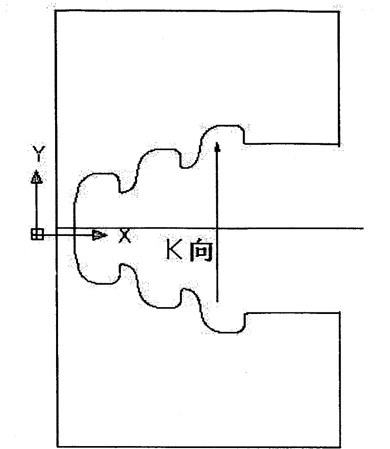
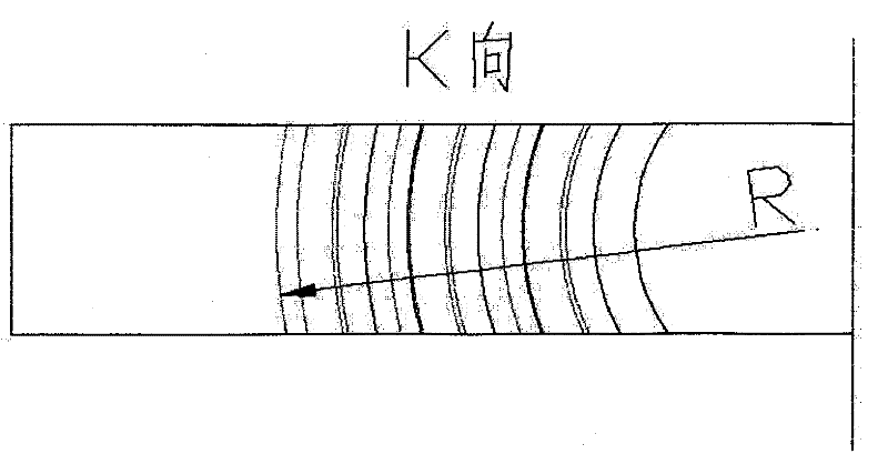
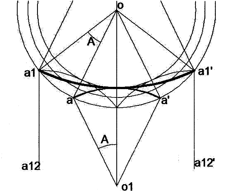
[0052]In order to ensure the accuracy of the fungus-shaped blade root groove line without over-cutting or under-cutting, it must be strictly ensured that the tool axis vector at the contact point between the cutter and the blade root arc surface is consistent with the normal direction of the arc surface during the cutting process, that is, : The tool axis vector always points to the arc center. In machine tools where the tool cannot swing, this requirement can only be achieved by the rotation of the workpiece and the linear movement of the tool. That is: when the tool cuts the inflection point of the arc curve, the tool axis coincides with the normal line of the point; when the tool cuts other points of the arc curve, the tool axis is parallel to the normal line of the point, and the tool axis due to the rotation of the workpiece Changes in the position of the point of contact with the arc are compensated by the linear movement of the tool. After equidistant interpolation of ...


PUM


Abstract

The present invention relates to a method for processing slots on a turbine rotor for mushroom-shaped blade roots. Slots for blade roots are milled by a profile milling cutter on a numerical control processing center. The numerical control processing center is provided with two rectilinear motion shafts and a rotating shaft at least. The rotating shaft is a lathe rotating table. The milling cutter is arranged on the cutter head of the main shaft of the numerical control processing center, and the milling cutter is driven by the shaft to rotate. The blade is fixed on the rotating table of the numerical control processing center, the radiant line of the blade is parallel with the main shaft and penetrates through the rotating center of the table, and the slots for blade roots are orientatedto the cutter head. The milling cutter is driven by the rotating table to rotate, the blade accordingly makes circumferential motion, and interpolation compensation is made for the circumferential motion angle by the rotating table. The two rectilinear motion shafts are parallel to the central plane of the mushroom-shaped blade roots, and interpolation compensation is made for displacements of the rotating table in the direction of the rectilinear motion shafts. Thus, when the milling cutter is used for cutting any processing point on an arc curve, the cutter axial vector is always on the normal line of the processing point and points to the arc center.

Description

technical field [0001] The invention relates to a processing method of steam turbine blades, in particular to a processing method of fungus-shaped blade-root grooves. Background technique [0002] Among the various blade root forms of steam turbine blades, the blade of the fungus-type blade is installed into the rotor impeller from the axial direction, and the mating surface between the blade root and the impeller is a unique arc-shaped groove, and its cross-sectional shape is shown in figure 1 , figure 2 , the arc radius R at the groove bottom point is the maximum radius. At present, special-purpose machine tools are used for processing. The characteristics are: the workpiece is fixed on the worktable by the fixture and cannot be moved, while the main shaft on which the milling cutter is installed is arranged on the turntable, which can rotate in a circle. When clamping the workpiece, adjust the processing surface to The distance from the center of rotation is equal to t...

Claims


Application Information

Patent Timeline
Patent Type & Authority Applications(China)
IPC IPC(8): B23C3/28
Inventor 周伶俐吴波钟成明胡剑华
Owner DONGFANG TURBINE CO LTD
Why Eureka
Try Eureka