Eureka AIR delivers breakthrough ideas for toughest innovation challenges, trusted by R&D personnel around the world.

Light emitting diode lamp

A technology of light-emitting diodes and lamps, which is applied to the semiconductor devices of light-emitting elements, light sources, lampshades, etc., which can solve the problems of luminous brightness of lighting devices, service life discount, poor energy-saving effect of lighting devices, impact on reliability of lighting devices, etc., to achieve The power supply requirements are simple and practical, easy to replace and install, and ensure the effect of beautifying the appearance

Inactive Publication Date: 2010-07-07
FU ZHUN PRECISION IND SHENZHEN +1
View PDF1 Cites 10 Cited by
  • Summary
  • Abstract
  • Description
  • Claims
  • Application Information

AI Technical Summary

Problems solved by technology

[0004] The application of high-power and high-brightness LEDs in the new light source of lighting must cooperate with a high-efficiency heat dissipation mechanism to minimize the junction temperature of the LEDs in order to take advantage of the above-mentioned advantages. Otherwise, the luminous brightness and service life of the lighting device will be greatly reduced, affecting all And will make the energy-saving effect of the lighting device not obvious, and directly impact the reliability of the lighting device, cause serious light decay and even make the lighting device invalid
[0005] Existing fluorescent lamps are mainly composed of lamp tubes, rectifiers and starters. Because the luminous efficiency is about several times that of tungsten bulbs, it has become the most commonly used lighting device at present. Its light is based on the principle of airtight gas discharge. The specific structure is included in The inner wall of the vacuum glass tube is coated with fluorescent substances, and the inside is filled with inert gas (such as Argon, Neon or Krypton) and mercury vapor, and the tube is conducted through a rectifier that can generate high voltage. The electric current excites mercury atoms to produce gas discharge, and releases ultraviolet light and heat during the discharge process, and releases visible light after absorbing ultraviolet light through the fluorescent substance; different fluorescent substances will emit different visible light; however, the existing fluorescent lamps The main gas discharge substances are toxic mercury and fluorescent substances, and the accumulated waste from long-term use of fluorescent lamps will seriously pollute the environment

Method used


Image

  • Light emitting diode lamp
  • Light emitting diode lamp
  • Light emitting diode lamp

Examples


Embodiment Construction

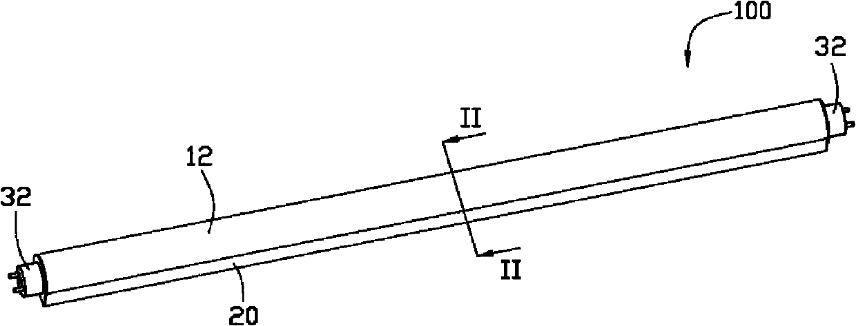
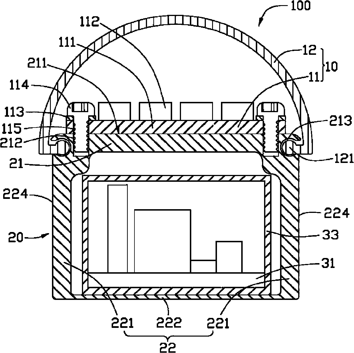
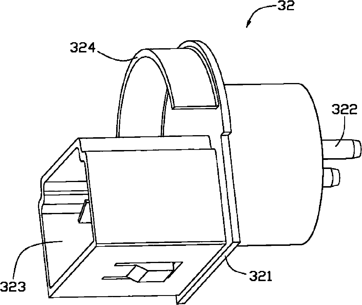
[0025] figure 1 is a three-dimensional assembly diagram of the first embodiment of the light emitting diode lamp 100 of the present invention, figure 2 yes figure 1 The sectional view at II-II, image 3 yes figure 1 The three-dimensional view of middle lamp holder 32, Figure 4 yes figure 1 The schematic diagram of the light-emitting diode lamp 100 docking with a lamp holder 40 is shown, Figure 5 will be multiple figure 1 The schematic diagram of the LED lamp 100 installed on a lamp panel 50 is shown. The LED lamp 100 mainly includes an optical part 10 , a heat dissipation part and an electrical part.

[0026] The optical part 10 includes at least one light-emitting diode light source 11 and a light guide cover 12. The light-emitting diode light source 11 is an integral molding, including a strip-shaped heat-conducting substrate 111, a number of luminous bodies 112 arranged on the heat-conducting substrate 111, and located on A plurality of electrodes (not shown) at ...


PUM


Abstract

The invention relates to a light emitting diode lamp comprising an optical part, an electrical part and a radiating part, wherein the optical part comprises at least one light emitting diode light source; the electrical part comprises at least one circuit board and two lamp holders and is for providing a driving power supply, a control circuit and power management which are needed by the light emitting diode light source; the radiating part comprises a long tubular radiator arranged between two lamp holders of the electrical part; the radiator comprises a radiating base and a radiating plate, and the radiating base and the radiating plate form a hollow tube body; the light emitting diode light source is arranged on the outer surface of the radiating base; the circuit board of the electrical part is arranged in the hollow tube body of the radiator; and heat produced by the light emitting diode is transmitted to the radiating plate through the radiating base and dissipated by the radiating palate.

Description

technical field [0001] The invention relates to a semiconductor lighting device, in particular to a light emitting diode lamp. Background technique [0002] People's long-term over-reliance on fossil fuels not only causes energy shortages and high oil prices and affects economic development, but also increases the concentration of global carbon dioxide and harmful gas emissions, leading to abnormal climate caused by global warming, destruction of the ecological environment, and The harm to human existence is becoming more and more obvious. In order to sustainably manage the earth's ecological environment on which human beings depend, it is necessary to solve the energy crisis and environmental pollution problems at the same time. The development of new energy and renewable energy is the most important strategy to promote energy conservation and efficient use of energy , while traditional lighting consumes a considerable amount of energy, the development of lighting energy sa...

Claims


Application Information

Patent Timeline
Patent Type & Authority Applications(China)
IPC IPC(8): F21S2/00F21V23/00F21V29/00F21Y101/02
CPCF21V23/023F21V3/02F21V15/011F21V23/009F21K9/17F21V29/2256F21V19/0055F21K9/00F21Y2103/003F21Y2101/02F21V29/507F21V29/767F21K9/272F21Y2103/10F21Y2115/10F21K9/27
Inventor 刘泰健周桃平
Owner FU ZHUN PRECISION IND SHENZHEN
Why Eureka
Eureka Blog
Learn More