Method for jointly removing carbon dioxide and sulfur dioxide from smoke

A combined removal and carbon dioxide technology, applied in chemical instruments and methods, separation methods, chemical separation, etc., to achieve the effects of low energy consumption, wide application range, and sufficient mixing

Inactive Publication Date: 2010-07-21
SOUTHEAST UNIV
View PDF7 Cites 22 Cited by
  • Summary
  • Abstract
  • Description
  • Claims
  • Application Information

AI Technical Summary

Problems solved by technology

Sulfur dioxide has always been one of the most important pollutants in flue gas. Although the application of desulfurization technology is relatively mature at present, adapting ...

Method used


Image

  • Method for jointly removing carbon dioxide and sulfur dioxide from smoke
  • Method for jointly removing carbon dioxide and sulfur dioxide from smoke
  • Method for jointly removing carbon dioxide and sulfur dioxide from smoke

Examples


Embodiment 1

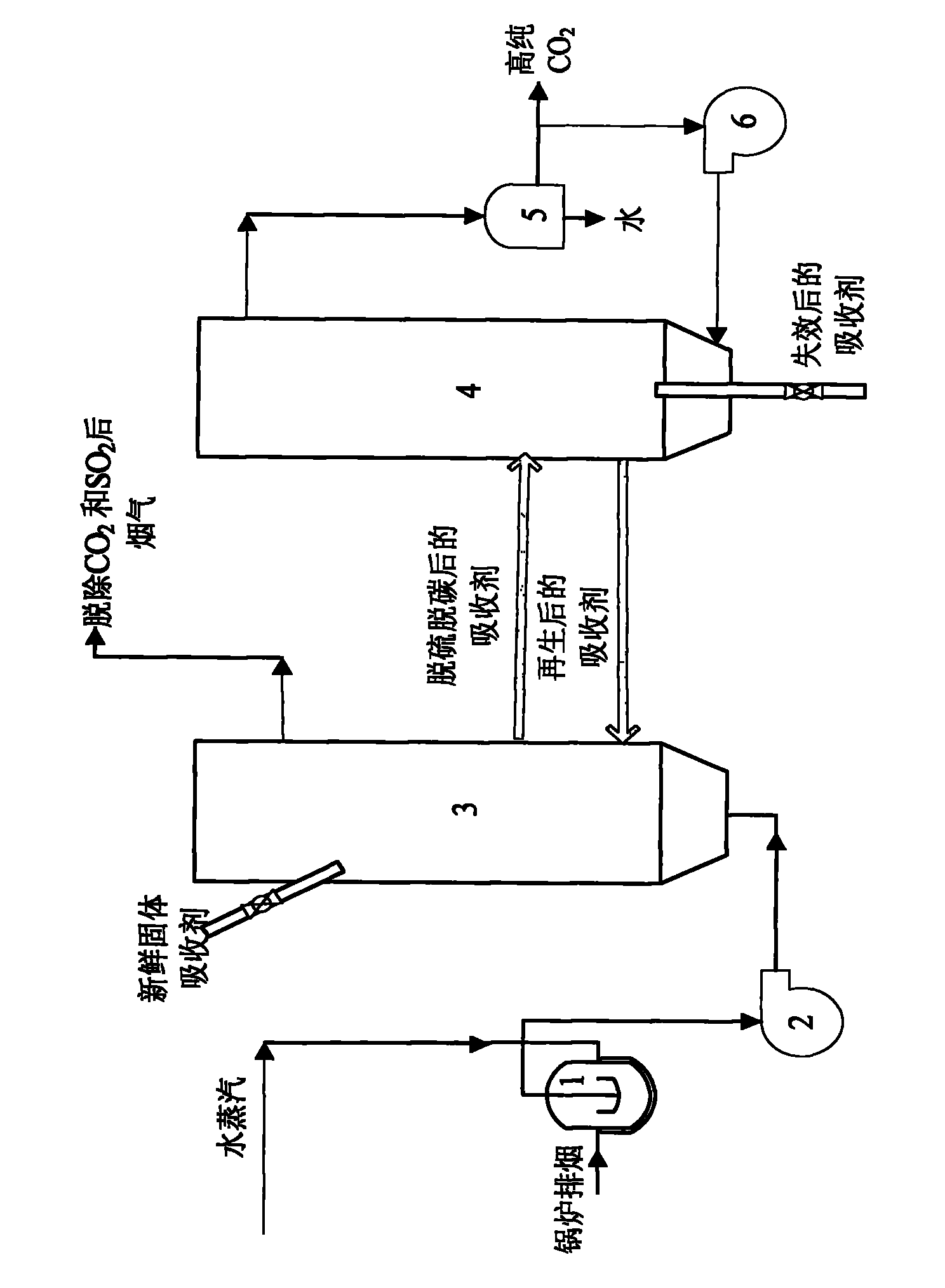
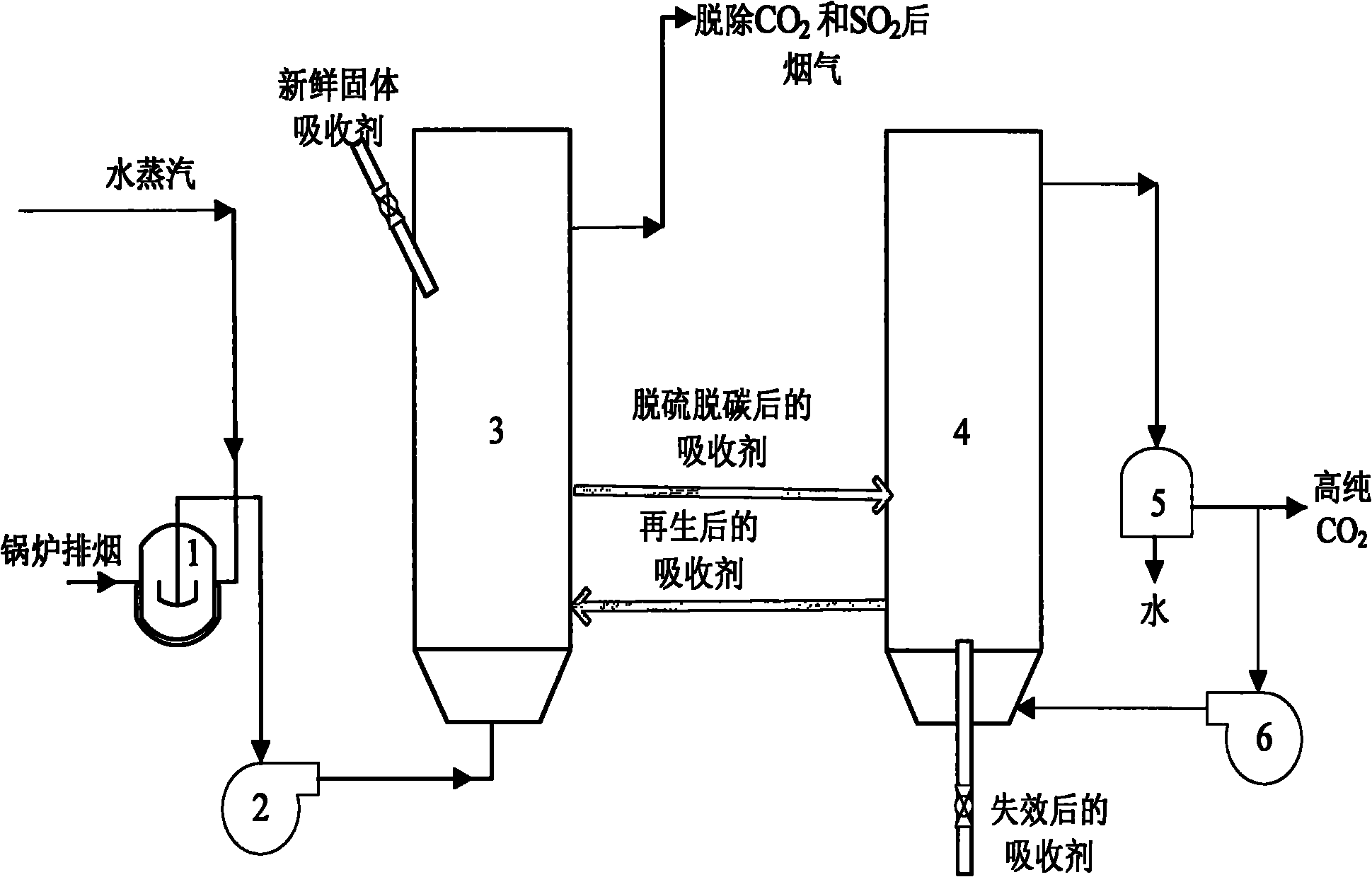
[0031] Power plant flue gas contains N 2 and part O 2 In addition, it contains about 10% water vapor and 10% to 20% CO 2 and 2500ppm SO 2 Wait. Put a certain amount of sodium carbonate or potassium carbonate or a mixture of sodium carbonate and potassium carbonate and activated alumina or activated carbon or magnesium oxide or a mixture of several substances to absorb absorbent particles prepared by impregnation or wet mixing or spraying in the flue gas In the absorption reactor, the temperature of the reactor is maintained between 60°C and 80°C, and the operation mode adopts the transport bed. When the flue gas passes through the reactor, CO 2 and SO 2 absorbed. CO removal 2 / SO 2 The final flue gas is directly discharged into the atmosphere through the flue and chimney. The reacted absorbent particles enter the regeneration reactor. The temperature of the regenerative bed reactor is maintained between 150°C and 300°C, and the operation mode adopts bubbling bed. Th...

Embodiment 2

[0033] Power plant flue gas contains N 2 and part O 2 In addition, it contains less water vapor, 10% to 20% of CO 2 and 2500ppm SO2 Wait. Set up a bypass on the exhaust pipe of the steam turbine, lead out a part of the low-pressure steam and adjust it to 10% through the flow regulating device and mix it with the flue gas, mix a certain amount of sodium carbonate or potassium carbonate or a mixture of sodium carbonate and potassium carbonate with activated alumina or activated carbon Or magnesium oxide or a mixture of several substances, the absorbent particles prepared by impregnation method, wet mixing method or spraying method are placed in the flue gas absorption reactor, and the temperature of the reactor is maintained between 60°C and 80°C. Bubble bed. When the flue gas passes through the reactor, CO 2 and SO 2 absorbed. CO removal 2 / SO 2 The final flue gas is directly discharged into the atmosphere through the flue and chimney. The reacted absorbent particles e...


PUM


Abstract

The invention discloses a method for jointly removing carbon dioxide and sulfur dioxide from smoke, which is mainly characterized in that: alkali carbonate is supported on a carrier to serve as a solid absorbent; under the condition of low temperature (60-100DEG C), CO2 and SO2 are jointly removed by utilizing vapor in the smoke in a smoke absorption reactor to generate bicarbonate and sulphite of alkali metals; the absorbent after the reaction is subjected to temperature rise (the temperature is raised to between 150 and 300 DEG C), the sulphite is not decomposed, and the bicarbonate is decomposed to generate carbonate, CO2 and vapor; after the carbonate, the CO2 and the vapor are condensed, high-purity CO2 can be separated out; the generated carbonate serves as the absorbent for recycling, and the SO2 is fixed in the solid absorbent and is discharged along with disabled materials after multiple circulation; and the smoke absorption reactor and an absorbent regeneration reactor can adopt various operating modes such as a fixed bed, a babble fluidization bed, a circulating bed and a transport bed. The method has the advantages of high efficiency of removing CO2/SO2, and simple equipment, and is an optimized scheme with low investment and energy consumption.

Description

technical field [0001] The present invention relates to CO in flue gas produced by fossil fuel combustion 2 removal and concentration methods, especially for further removal of SO 2 . Belongs to joint removal of CO 2 / SO 2 technology field. Background technique [0002] With the development of the world economy, the consumption of energy and the resulting emission of greenhouse gases are increasing day by day, and a series of effects of global warming are gradually emerging. In 2005, the "Kyoto Protocol", aimed at limiting greenhouse gas emissions in various countries, came into force. Carbon dioxide emission reduction has become a research hotspot in various countries. Therefore, it is particularly important to research and develop carbon dioxide emission reduction technologies suitable for power plants. The research and application of post-combustion flue gas removal of carbon dioxide technology in my country has broad market prospects. Sulfur dioxide has always be...

Claims


Application Information

Patent Timeline
IPC IPC(8): B01D53/82B01D53/50B01D53/62B01D53/96
CPCY02C10/04Y02A50/20Y02C20/40
Inventor 陈晓平吴烨赵传文赵长遂梁财
Owner SOUTHEAST UNIV
Why Eureka
Try Eureka