
Phenol and cyanogen waste water physical chemical method control process and equipment

A waste water and equipment technology, applied in the direction of water pollutants, chemical instruments and methods, water/sewage multi-stage treatment, etc., can solve the problems that waste water cannot reach

Active Publication Date: 2010-07-21
JINAN METALLURGICAL CHEM EQUIP CO LTD
View PDF5 Cites 14 Cited by
  • Summary
  • Abstract
  • Description
  • Claims
  • Application Information

AI Technical Summary

Problems solved by technology

It has a good treatment effect, but the treated wastewater still cannot meet the requirements stipulated in the "Access Conditions for Coking Industry" (revised in 2008) (GB8978-1996)

Method used


Image

  • Phenol and cyanogen waste water physical chemical method control process and equipment
  • Phenol and cyanogen waste water physical chemical method control process and equipment

Examples


Embodiment 1

[0049] Embodiment 1, a kind of phenol cyanide-containing waste water physicochemical treatment process is characterized in that: its main process is

[0050] Wastewater containing phenol and cyanide→air flotation method for oil removal→iron condensation method for cyanide and sulfur removal→extraction and phenol removal→tubular furnace method for ammonia distillation→decompression method for NH removal 3 -N, phenol and organic matter, sulfur cyanide and other pollutants → ozone catalytic oxidation → standard waste water is used for coke quenching

[0051] The ferrocoagulation method for H removal 2 S, HCN is carried out in two steps. The first step is the H in the wastewater 2 S and HCN first react with active iron in the reactor to generate FeS and Fe 2 [Fe(CN) 6 ] or Fe 4 [Fe(CN) 6 ]3 precipitates, thus most of the H 2 S, HCN removal, the second step: to speed up and the remaining H 2 S, HCN reaction speed, add coagulant and flocculant to achieve the purpose of separ...

Embodiment 2

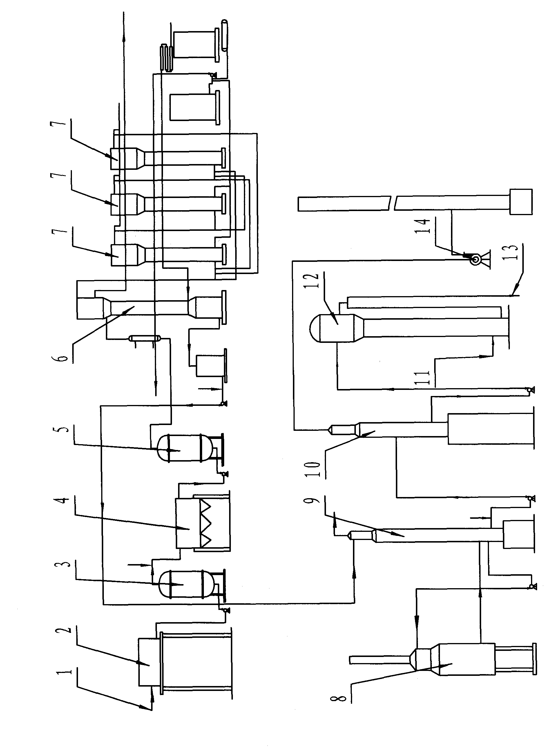
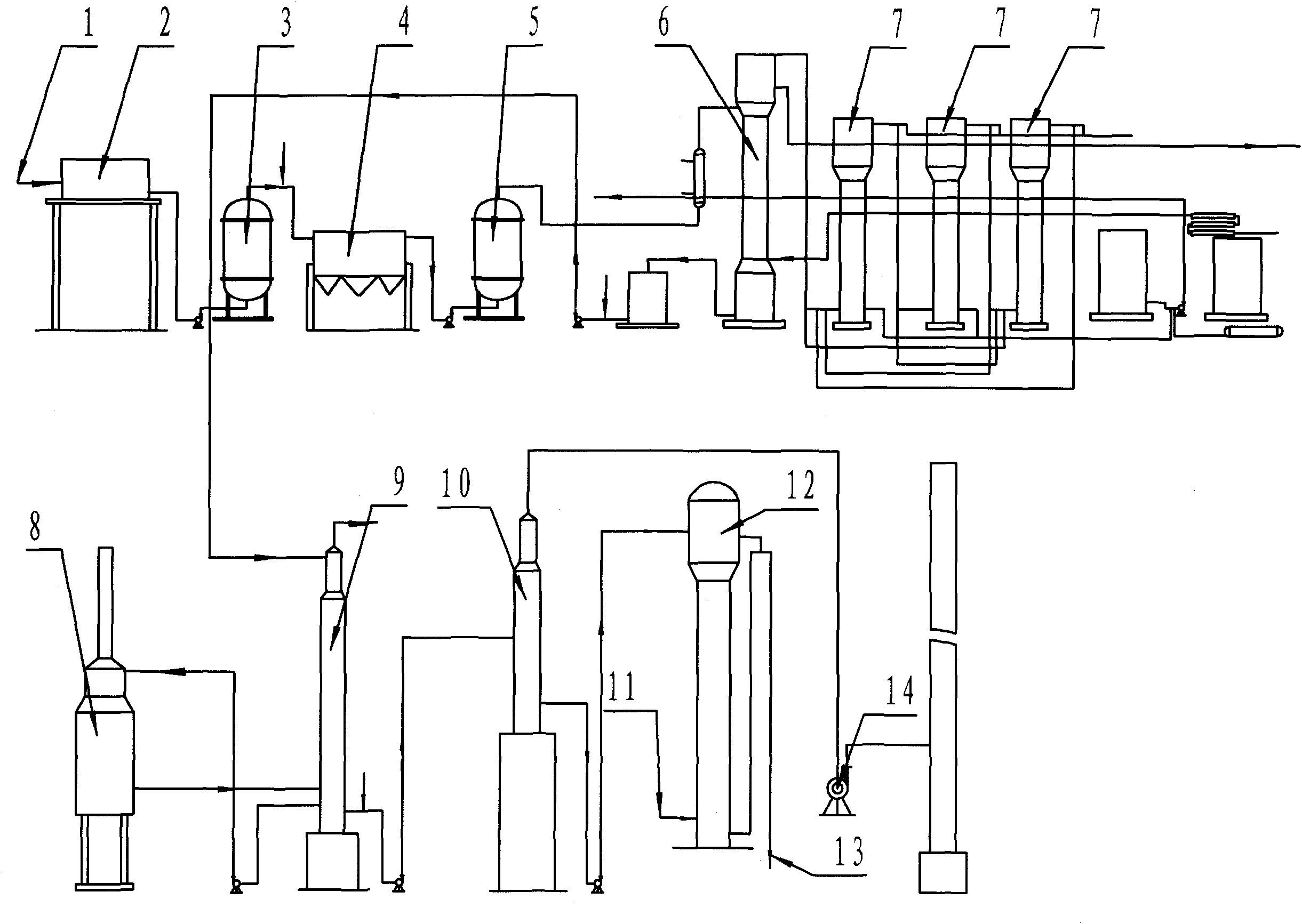
[0055] Embodiment 2, as shown in the figure: the equipment used in the treatment process of phenol cyanide wastewater physicochemical method, its structure is: mainly by successively connected air flotation and degreasing equipment, ferrocondensation and cyanide and sulfur removal equipment, extraction and phenol removal equipment, distillation Composition of deamination equipment. Ferrocoagulation cyanide and sulfur removal equipment is composed of ferrocoagulation reactor, reaction clarifier and filter connected in sequence. The extractive phenol removal equipment includes an extraction tower and multiple alkali washing towers connected in series.

[0056] The distillation denitrification equipment includes an ammonia distillation tower connected to a tubular heating furnace and a decompression phenol cyanide stripping tower connected to its outlet, the stripping tower is connected with a catalytic oxidation tower, and the catalytic oxidation tower is connected with a treate...


PUM


Abstract

The invention discloses phenol and cyanogen waste water physical chemical method control process and equipment, which belongs to the treating technology of waste water or sewage, in particular to a waste water multi-stage treating technology including at least one chemical treating step. The phenol and cyanogen waste water physical chemical method control process is characterized in that the main process flow comprises oil removal of the waste water containing phenol and cyanogen by an air floating method, cyanogen removal and desulphurization by ferrous condensation, extraction to remove phenol, ammine evaporation by a tube type furnace method, evaporation to remove contaminants of NH3-N, phenol, organic matters, sulphur, cyanogen and the like by a depressurizing method, and catalyzing and oxidizing by ozone, and then the waste water achieving the standard is obtained for coke quenching. By the technology for treating the waste water containing phenol and cyanogen, the invention achieves the advantages of good treating effect, little investment, low running cost, changing wastes into resources, strong weather adaptability, and the like.

Description

technical field [0001] The invention belongs to the treatment technology of waste water or sewage, in particular the multi-stage treatment technology of waste water with at least one chemical treatment step. Background technique [0002] The core technology of the traditional treatment of coking phenol cyanide wastewater is: ammonia distillation + biochemical (A / O method A 2 / O method or A 2 / O 2 Method) Due to the large amount of coking phenol cyanide wastewater and its high pollutant content, cyanide, NH3-N, polycyclic aromatic hydrocarbons, and heterocyclic content are more difficult to biochemically degrade, so that the treatment effect is not very stable. Traditional coking wastewater treatment technology has continuously increased the amount of wastewater in the wastewater treatment process. For example, the wastewater in the ammonia distillation process increased by 20-22%. Before biochemical treatment, it was forced to dilute the industrial water and increased by 1...

Claims


Application Information

Patent Timeline
Patent Type & Authority Applications(China)
IPC IPC(8): C02F9/04C02F101/18C02F101/34
Inventor 季广祥姜爱国王登富张友棣陈善龙赵杰孙兆俊
Owner JINAN METALLURGICAL CHEM EQUIP CO LTD
Learn More