
Method for manufacturing image display device, image display device and liquid crystal display device

A liquid crystal display device and image display technology, which is applied to identification devices, optical filters, optics, etc., can solve problems such as peeling off, reduced productivity, and poor workability

Inactive Publication Date: 2010-07-21
HITACHI CHEM CO LTD
View PDF6 Cites 27 Cited by
  • Summary
  • Abstract
  • Description
  • Claims
  • Application Information

AI Technical Summary

Problems solved by technology

[0007] However, in this case, since there is a gap between the protective panel and the polarizer, there is a problem that the reflection of the scene on the image display surface is accompanied by reflections at three surfaces in total on both sides of the protective panel and the surface of the polarizer. Occurs intensely, reduces visual recognition in bright places
[0019] Even if the method of Patent Document 6 is adopted, the problem of entrainment of air bubbles still exists as a problem that needs to be solved separately, and there is a problem that in the above-mentioned method (1), it is necessary to supply the liquid resin in a quantitative manner, and if it is not the case, then It is necessary to deal with the excess resin that bleeds out; in the method (2), it takes time to flatten and homogenize the resin, and it is necessary to deal with the oozing resin, or the treatment takes time, etc., and the workability deteriorates; according to the method (3), the manufacturing device and Complicated tasks, etc.
As a result, there is a problem that the production management of the image display device is complicated or the productivity is lowered.
Furthermore, in either method, the spacer, the molding frame, or the protective panel must be processed into a special shape, and an inexpensive flat plate cannot be used.
In addition, air holes remain around the discharge passage and the injection hole. Even in the outer peripheral part that does not directly affect the image, there is a problem that the protective panel is likely to be lifted or peeled off due to the air bubbles in a long-term use environment.
In addition, there is a problem that it is necessary to perform wiping work for each panel as a treatment method for the oozing liquid resin.

Method used


Image

  • Method for manufacturing image display device, image display device and liquid crystal display device
  • Method for manufacturing image display device, image display device and liquid crystal display device
  • Method for manufacturing image display device, image display device and liquid crystal display device

Examples


Embodiment 1

[0483] (Synthesis of transparent organic matter)

[0484] Add 100 parts by weight of 2-ethylhexyl acrylate and 80 parts by weight of toluene to a reaction vessel equipped with a cooling tube, a thermometer, a stirring device, a dropping funnel, and a nitrogen injection pipe, and bubble with nitrogen at a capacity of 100 ml / min. , 0.5 parts by weight of azobisisobutyronitrile dissolved in 20 parts by weight of toluene was added dropwise. After the dropwise addition was completed, a polymerization reaction was performed at 70° C. for 2 hours. Then, toluene was removed to obtain a 2-ethylhexyl acrylate polymer having a weight average molecular weight of 200,000.

[0485] Add 49.5 parts by weight of the resulting 2-ethylhexyl acrylate polymer, 49.5 parts by weight of 2-ethylhexyl acrylate, 1.0 parts by weight of 1,6-hexanediol diacrylate, 0.5 parts by weight of IRGACURE184 (cibasine Chemical Co., Ltd. trade name), stirred to form a uniform solution (viscosity 2900mPa·s), to obta...

Embodiment 2

[0492] A liquid crystal display device was obtained as in Example 1, except that an open-cell polyurethane sponge (product name; Sofras, IAON Co., Ltd.) with a porosity (void ratio) of 83% and a thickness of 1 mm was used as the frame material.

[0493] At this time, V 1 +V f x(R / 100)=1.72ml.

Embodiment 3

[0495] In addition to using an open-cell polyethylene sponge with a porosity (void ratio) of 53% and a thickness of 0.8mm (product name; Filtaren Sitto F-100, manufactured by Filtaren Co., Ltd.), the resin filling amount L = 1.2ml Otherwise, a liquid crystal display device was obtained in accordance with Example 1.

[0496] At this time, V 1 +V f x(R / 100)=1.22ml.


PUM

PropertyMeasurementUnit
thicknessaaaaaaaaaa
thicknessaaaaaaaaaa
thicknessaaaaaaaaaa

Abstract

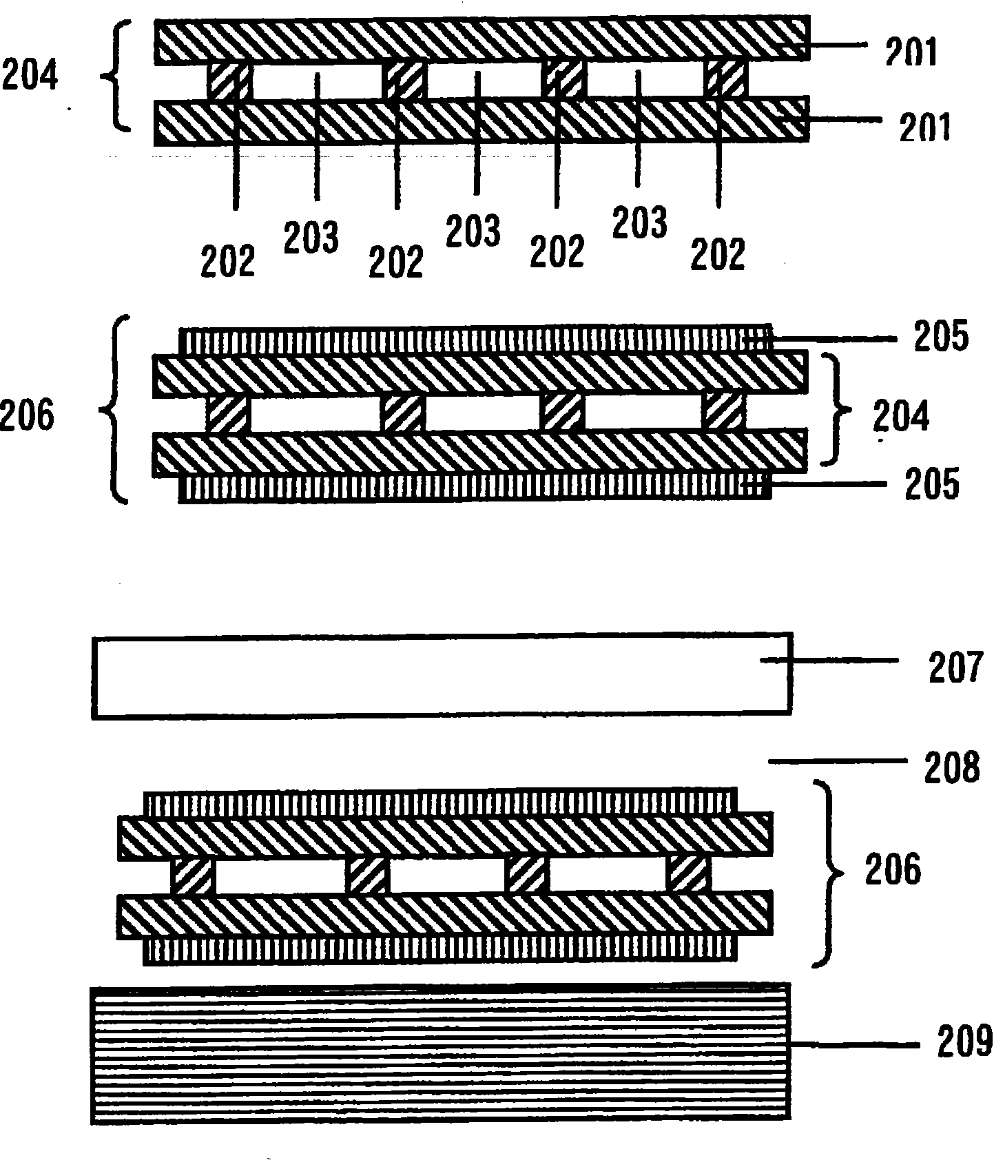
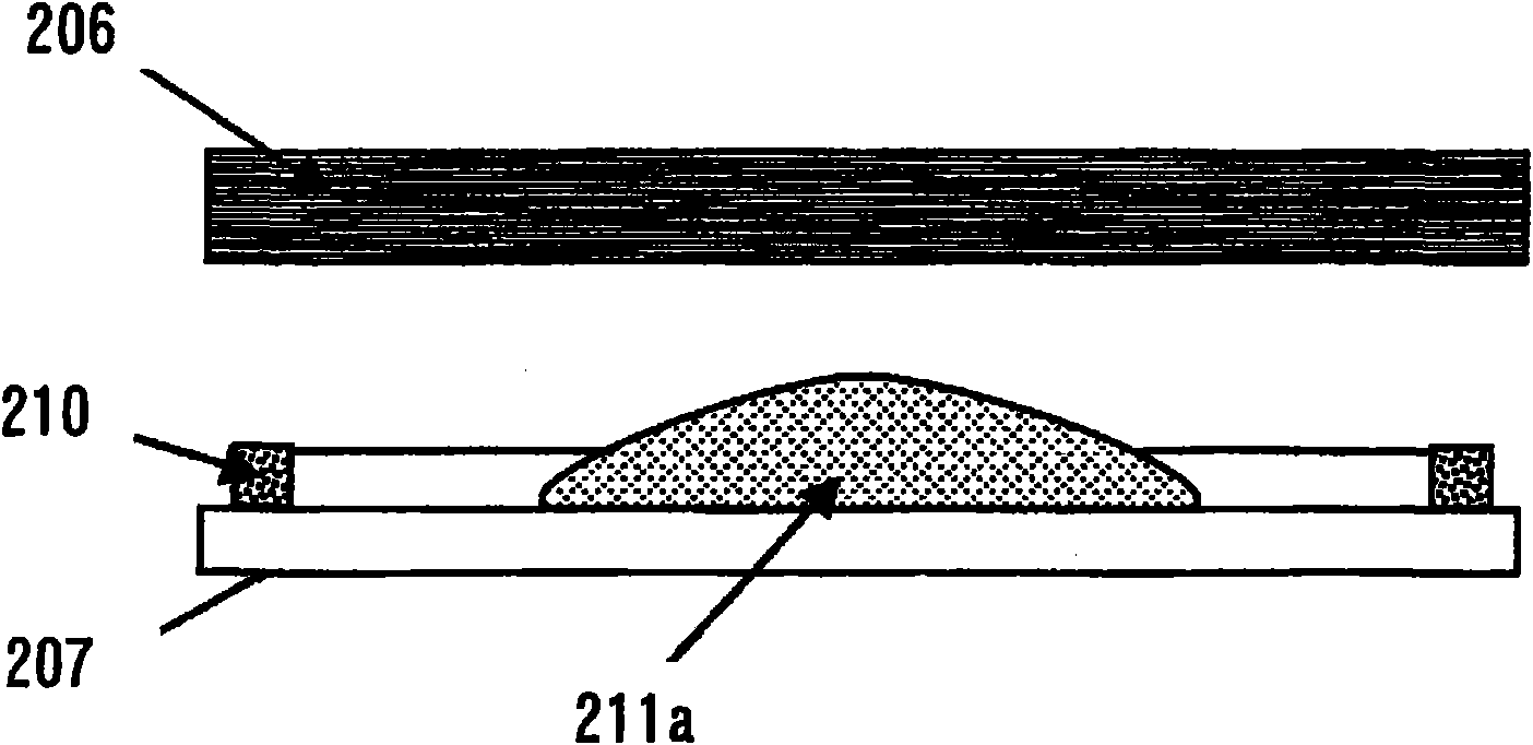
Provided is a method for manufacturing an image display device having improved impact resistance by arranging a transparent resin layer between an image display panel and a protection panel. By the method, the transparent resin layer having no air bubble can be manufactured with excellent productivity. In the method for manufacturing the image display device, a transparent organic medium is arranged by being adhered between the image display panel and the protection panel arranged on the view side of the image display panel, without having an air layer in between. On the image display panel or the protection panel, a frame having many spaces through which air can pass is arranged. The method includes a step of injecting the liquid-state transparent organic medium inside an area surrounded by the frame on the image display panel or the protection panel; a step of placing the image display panel or the other panel of the protection panel on the frame; and a step of solidifying the liquid-state transparent organic medium.

Description

technical field [0001] The present invention relates to an image display device having an image display panel and a protective panel, a manufacturing method thereof, and a liquid crystal display device. The image display panel includes a plasma display panel (PDP), a liquid crystal display (LCD), an organic EL display (OLED), a field emission display (FED), and the like. In addition, it can be used on the surface of a panel displaying still images such as photographs or paintings, in addition to the above-mentioned display panels. More specifically, the present invention relates to an image display device having a structure for protecting the image display panel from various usage environments or usage states without impairing the visibility of the image display panel, and a method for manufacturing the image display device. . Background technique [0002] A typical image display device includes a liquid crystal display device. A liquid crystal panel used in a liquid crys...

Claims


Application Information

Patent Timeline
Patent Type & Authority Applications(China)
IPC IPC(8): G09F9/00G02F1/13G02B1/11G02B1/111G02B1/18G02B5/20G02B5/30G02F1/1333G02F1/1335
CPCG02F1/133308G02F2201/50
Inventor 高桥亨高桥惠佐佐木洋杉林真已子富冈安高根信明河合宏政
Owner HITACHI CHEM CO LTD
Learn More