Highly-efficient air energy water source heat pump integrated unit

A high-efficiency air and water source heat pump technology, applied in refrigerators, compressors, refrigeration components, etc., can solve the problems of increasing the tube wall, increasing the air flow resistance, troublesome management and maintenance, etc., to achieve low surface vapor pressure, efficient operation and use , the effect of stable solution properties

Inactive Publication Date: 2010-07-28
HUNAN YUANHENG TECH CO LTD
View PDF0 Cites 10 Cited by
  • Summary
  • Abstract
  • Description
  • Claims
  • Application Information

AI Technical Summary

Problems solved by technology

As the outdoor air temperature drops, the COP value of the air-cooled heat pump unit will drop significantly. When the outdoor temperature drops to a certain limit (usually -5 to -10°C, a few equipment can reach -15°C), the unit will be difficult to start , does not work properly
[0007]2. Even if the outdoor temperature in winter is -5~0℃, the heat pump can be started, but since the surface temperature of the outdoor heat exchanger coil is below 0℃ at this time, the replacement The surface of the heater will cause the water vapor in the air to condense and frost on the surface of the coil
The increase in the thickness of the frost layer on the surface of the heat exchanger not only increases the additional thermal resistance of the tube wall, reduces the heat transfer coefficient of the heat exchanger, and reduces the heat transfer efficiency, but also narrows the air flow path of the coil, hinders convection, and increases air flow resistance , resulting in an increase in fan power
[0008]3. In the case of frost, air-cooled heat pump units generally use electric heating or reverse cycle to defrost. The former of these two defrosting methods consumes a lot of power , when the latter defrosts, the air-cooled heat pump not only does not supply heat to the room, but also extracts the defrosting heat from the room, resulting in a loss of 6-12% of the heat supply
[0010] Although the traditional air-conditioning method can meet the cooling and heating requirements under normal circumstances, the air-conditioning machine room occupies a large area, the initial investment is high, the operating cost is high, and the installation is complicated , large amount of engineering, strong professionalism, cumbersome construction, troublesome management and maintenance, which is not conducive to large-scale application

Method used


Image

  • Highly-efficient air energy water source heat pump integrated unit
  • Highly-efficient air energy water source heat pump integrated unit
  • Highly-efficient air energy water source heat pump integrated unit

Examples


Embodiment 1

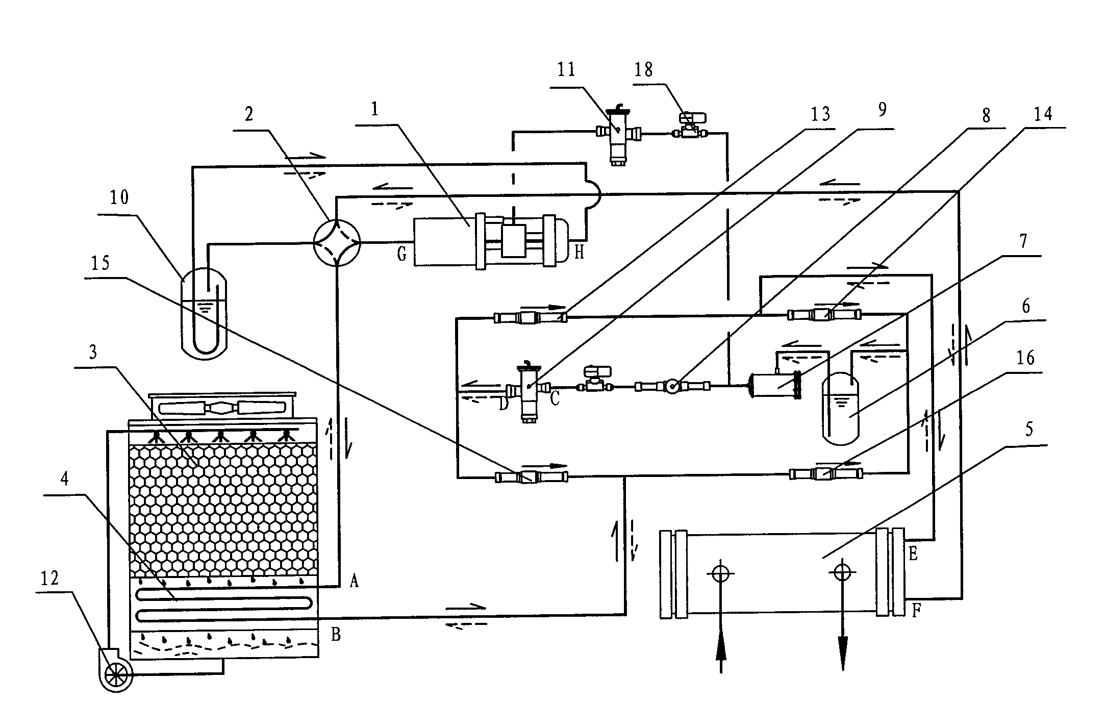
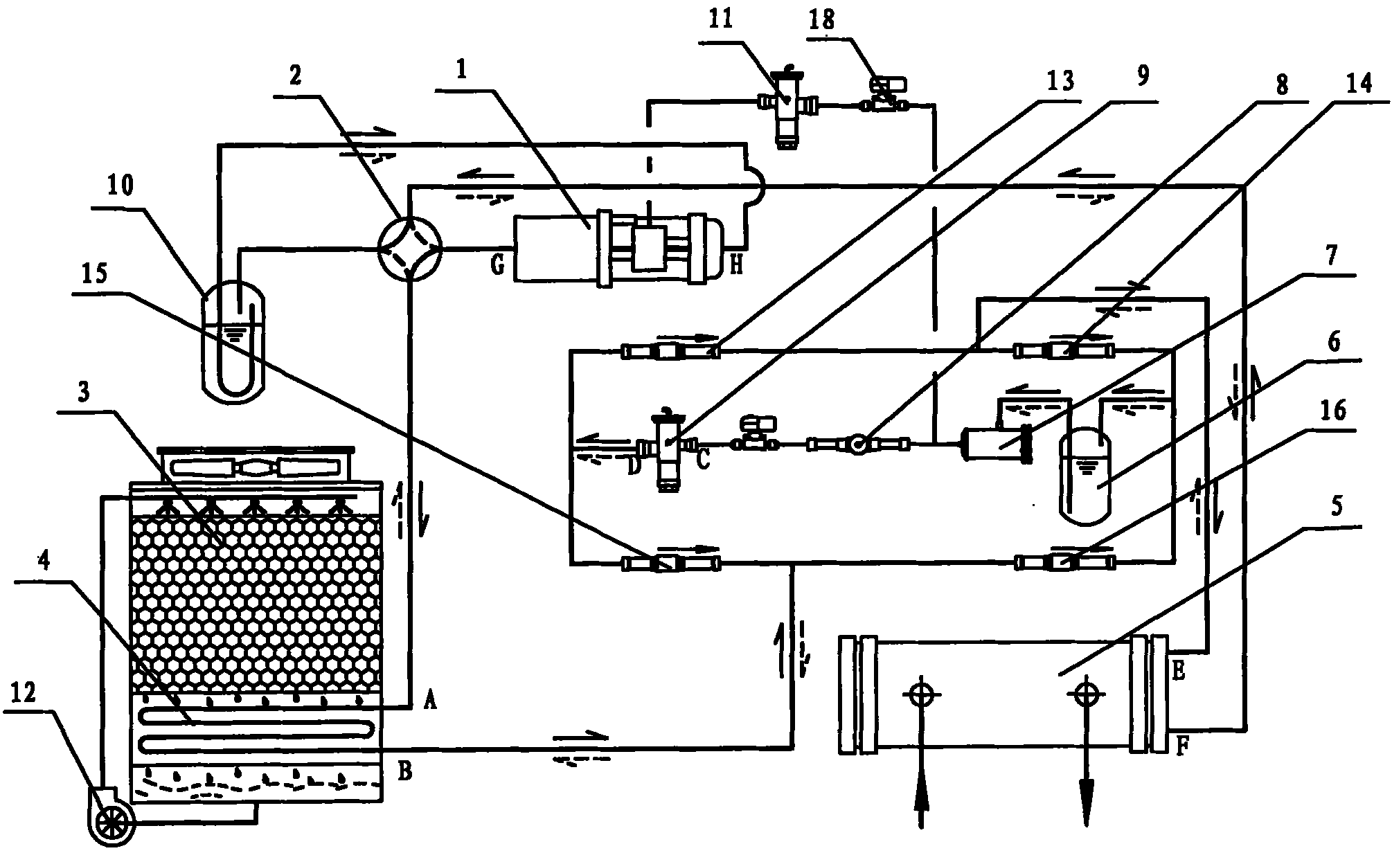
[0034] Embodiment 1: see attached figure 1 , Embodiment 1 of the present invention consists of a compressor 1, a four-way reversing valve 2, a heat exchange tower 3, a first heat exchanger 4, a second heat exchanger 5, a liquid reservoir 6, a dry filter 7, and a sight glass 8. An expansion valve 9, a gas-liquid separator 10, a liquid injection expansion valve 11, a water pump 12, check valves 13, 14, 15, 16, and a solenoid valve 18 form.

[0035]The first heat exchanger 4 is installed in the heat exchange tower 3; the outlet G of the compressor 1 is connected to the inlet A of the first heat exchanger 4 through the four-way reversing valve 2, so The outlet B of the first heat exchanger 4 is divided into two paths, one path is connected with the inlet C of the expansion valve 9 through the check valve 16, and the other path is connected with the outlet D of the expansion valve 9 through the check valve 15; The outlet D of the expansion valve 9 is connected to the inlet E of th...

Embodiment 2

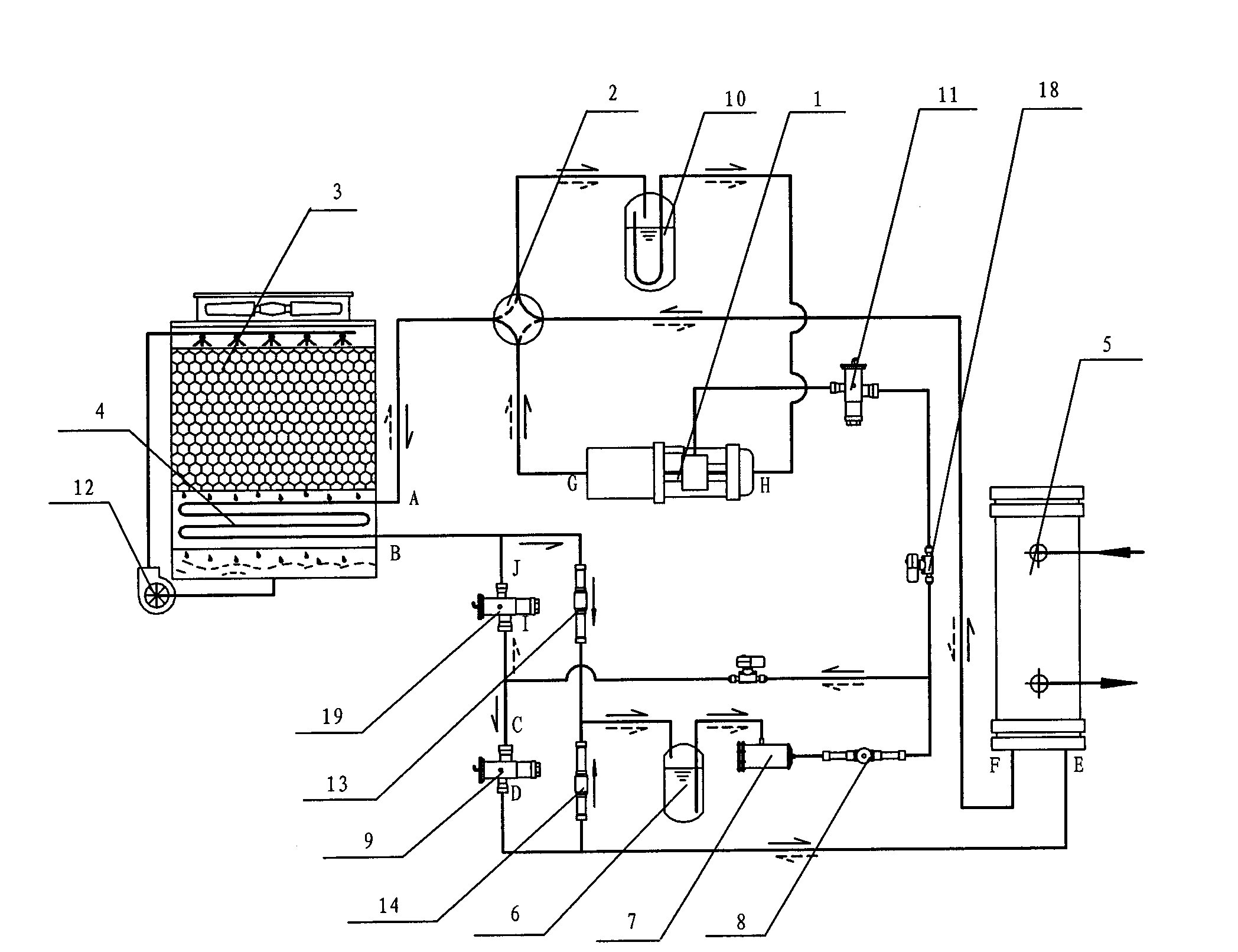
[0042] Embodiment 2: see attached figure 2 , Embodiment 2 of the present invention consists of a compressor 1, a four-way reversing valve 2, a heat exchange tower 3, a first heat exchanger 4, a second heat exchanger 5, a liquid reservoir 6, a dry filter 7, and a sight glass 8. Refrigeration thermal expansion valve 9, heating thermal expansion valve 19, liquid injection expansion valve 11, water pump 12, check valves 13, 14, and solenoid valve 18. Valves 15 and 16 are replaced by expansion valve 19. The outlet B of the first heat exchanger 4 is divided into two paths, and one path is connected to the inlet C of the expansion valve 9 and the inlet I of the expansion valve 19 respectively through the check valve 13. The other way is connected to the outlet J of the expansion valve 19; the outlet D of the expansion valve 9 is connected to the inlet E of the second heat exchanger 5, and the inlet E of the second heat exchanger 5 is also passed through a non-return The valve 14 is...


PUM


Abstract

The invention relates to a highly-efficient air energy water source heat pump integrated unit which comprises a compressor, a first heat exchanger, a second heat exchanger, a heat exchange tower, a water pump, an expansion valve and a reversing valve, wherein the first heat exchanger is arranged in the heat exchanger tower; an output of the compressor is connected with an inlet of the first heat exchanger through the reversing valve, an outlet of the first heat exchanger is divided into two paths which are respectively connected with an inlet and an outlet of the expansion valve; the outlet of the expansion valve is connected with an inlet of the second heat exchanger through a one-way valve, an inlet of the second heat exchanger is also connected with the inlet of the expansion valve; the outlet of the second heat exchanger is connected with the inlet of the compressor; and the heat exchanger tower is provided with the water pump for providing cooling media circulating power. The invention has simple structure, small volume, high energy efficiency ratio, lower cost, easy installation and construction, lower cost of the operation and convenient maintenance, thereby being an air conditioner cooling, heating and healthy hot water making mode with development potential, and being suitable for industrialized application. The invention can solve the problems of instability factor of weather with an air source, limitation of ground and water sources, overhigh initial cost and the like.

Description

technical field [0001] The invention discloses a high-efficiency air energy water source heat pump integrated unit, which belongs to the application field of air source heat pump and water source heat pump systems. Background technique [0002] At present, the energy problem has become the main constraint faced by the global economic development. With the development of the economy and the improvement of people's living standards, building energy consumption has accounted for more than 30% of the total energy consumption of the whole society, and is still growing at a relatively rapid rate. In building energy consumption, the energy consumption of air-conditioning for cooling in summer and heating in winter accounts for the largest proportion. The continuous innovation of air-conditioning technology will have great significance for energy saving and emission reduction. [0003] Solar energy has the characteristics of intermittency and instability, which greatly restrict the...

Claims


Application Information

Patent Timeline
Patent Type & Authority Applications(China)
IPC IPC(8): F25B13/00
CPCF25B13/00F25B2339/047F25B2339/041F25B2313/02741
Inventor 彭建国吴加胜汪迪文曾向阳
Owner HUNAN YUANHENG TECH CO LTD
Why Eureka
Try Eureka