Insulated switching power supply device

一种开关电源、绝缘型的技术,应用在输出功率的转换装置、电气元件、调节电变量等方向,能够解决大型化高成本化、大励磁电感、大型成本等问题

Active Publication Date: 2010-07-28
MURATA MFG CO LTD
View PDF5 Cites 6 Cited by
  • Summary
  • Abstract
  • Description
  • Claims
  • Application Information

AI Technical Summary

Problems solved by technology

[0018] However, in order to transmit the square wave of the switching frequency with low loss, the driving transformer T4 needs relatively large magnetizing inductance (for example, 100μH or more)
Therefore, the drive transformer T4 needs the primary coil and the secondary coil with a large number of turns, and becomes a large and expensive component.
[0019] In addition, in order to suppress the surge voltage of the power switch Q1, a voltage clamping circuit is installed on the secondary side of the main transformer T1. If the voltage clamping circuit is to be driven from the primary side circuit through the driving transformer, the driving transformer needs to meet safety standards. Necessary withstand voltage (for example, DC1500V), which leads to further problems of size and cost

Method used


Image

  • Insulated switching power supply device
  • Insulated switching power supply device
  • Insulated switching power supply device

Examples


no. 1 Embodiment approach 》

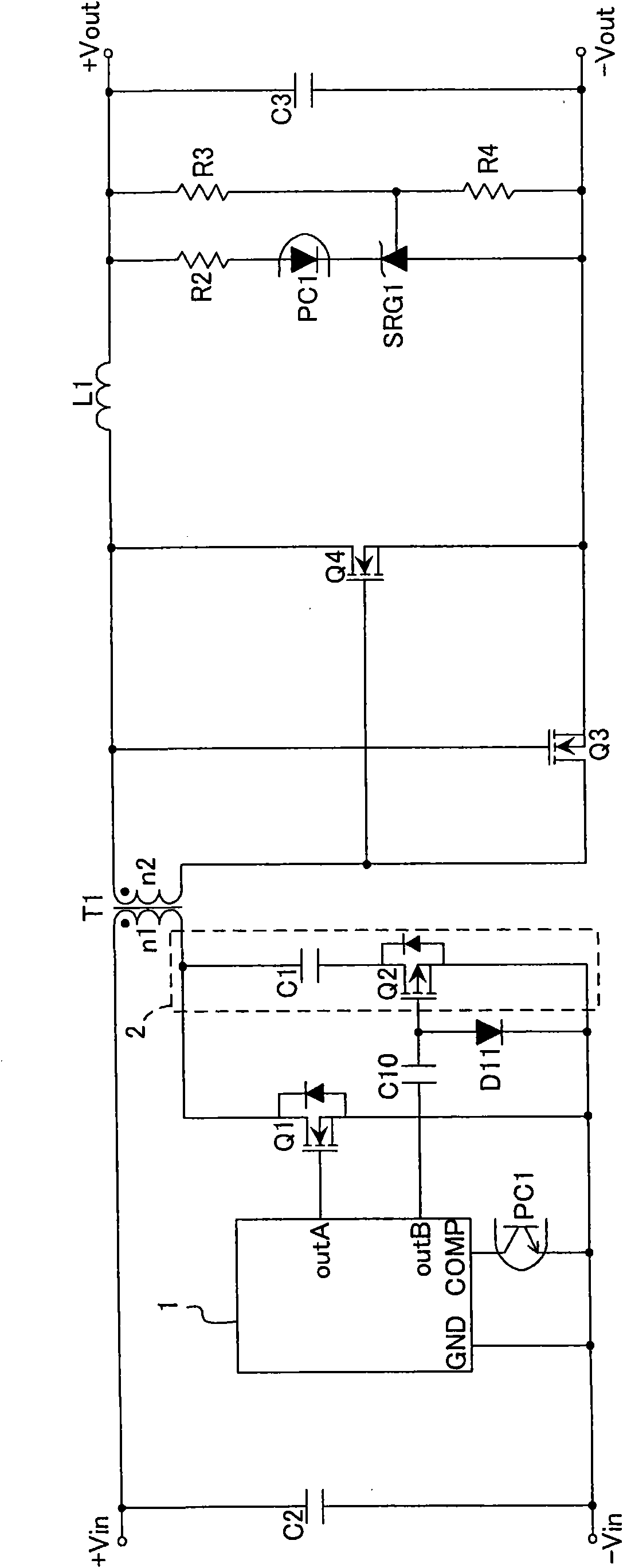
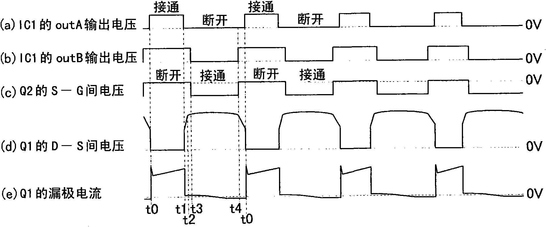
[0082] Figure 5 It is a circuit diagram of the isolated switching power supply device 101 according to the first embodiment. Figure 6 The waveform diagram of its various parts, Figure 7 It is a diagram showing the configuration of a composite transformer used in the above-mentioned isolated switching power supply device 101 .

[0083] Figure 5Here, a series circuit of a clamp capacitor C1 and a clamp switch Q2 is connected in series with the primary coil n1 of the main transformer T1 to form a voltage clamp circuit 2 . The clamp switch Q2 is an N-channel MOSFET, and a parasitic diode is provided in parallel. The switch control circuit 1 is a PWM control IC for driving an active clamp converter. The switch control circuit 1 includes a power switch drive terminal outA, a clamp switch drive terminal outB, a feedback signal input terminal COMP, and a ground terminal GND. The circuit connected with the voltage clamping circuit 2 and providing a control signal to the clampi...

no. 2 Embodiment approach 》

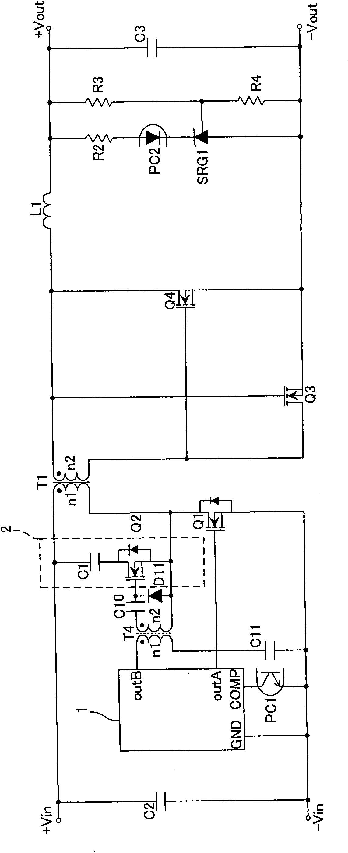
[0110] Figure 8It is a circuit diagram of the isolated switching power supply device 102 according to the second embodiment. Figure 9 Waveform diagram of each part. The structure of the primary side of the main transformer T1 is the same as that in the first embodiment Figure 5 The structure shown is the same. The secondary side of the main transformer T1 includes a rectifier diode D5, an output smoothing capacitor C3, resistors R2, R3, and R4, a light emitting diode of the photocoupler PC1, and a shunt regulator SRG1.

[0111] The isolated switching power supply device 102 according to the second embodiment constitutes an active-clamp-flyback converter. Operations of the clamp switch drive circuit and output voltage feedback are substantially the same as those of the first embodiment, so the operation of power conversion will be described here.

[0112] First, the DC voltage applied between +Vin and -Vin of the DC input power source is smoothed by the input smoothing c...

no. 3 Embodiment approach 》

[0116] Figure 10 It is a circuit diagram of the isolated switching power supply device 103 according to the third embodiment. Figure 11 Waveform diagrams of its various parts. The isolated switching power supply device 103 according to the third embodiment constitutes an asymmetrically controlled half-bridge converter. This "asymmetrical control" is a control method in which both the power switch Q1 and the clamp switch Q2 are driven at complementary timing while the dead time that both the power switch Q1 and the clamp switch Q2 are off. When the pulse width of the power switch Q1 becomes wider, the clamp switch Q1 When the pulse width of the bit switch Q2 is narrowed and the pulse width of the power switch Q1 is narrowed, PWM control is performed as if the pulse width of the clamp switch Q2 is widened. Such as Figure 11 As shown, the operation waveform is similar to that of the active-clamp-flyback converter shown in the second embodiment.

[0117] Figure 10 , the s...


PUM


Abstract

The invention provides an insulated switching power supply device. On the primary circuit side are disposed an input smoothing capacitor (C2), a switching control circuit (1), a high-side driver (3), a low-side power switch (Q1), a high-side power switch (Q7), capacitors (C5,C6), and edge signal-generating circuits (5,6). A symmetrical control half bridge converter is thus provided. The secondary circuit side has a voltage clamping circuit (2) including a clamp capacitor (C1), a clamp switch (Q2) and a diode (D6). Even though the clamping switch adopts a N-channel MOSFET, a pulse transformer capable of at least transmitting the edge siganl of the pulse with less magnetic inductance value can be used to drive the clamping switch.

Description

technical field [0001] This invention relates to a main transformer that transmits power from the primary side to the secondary side, and a power switch that interrupts the current flowing from the DC input power source through the primary coil of the main transformer to output a desired DC voltage or DC current. type switching power supply unit. Background technique [0002] Conventionally, zero-voltage switching (ZVS) reduces switching loss and improves circuit efficiency. For example, as disclosed in Patent Document 1, an isolated switching power supply device equipped with a voltage clamp circuit is used. [0003] An isolated switching power supply device including such a voltage clamp circuit is often used when the output voltage is lower than the input voltage. figure 1 An example in which this isolated switching power supply device is constructed by the prior art is shown in . also, figure 2 The waveform diagram of each part is shown in . [0004] figure 1 In th...

Claims


Application Information

Patent Timeline
Patent Type & Authority Applications(China)
IPC IPC(8): H02M3/335
CPCH02M3/33538H02M1/34H02M2001/342H02M3/3376H02M3/33523Y02B70/1491H02M1/0064H02M1/342Y02B70/10
Inventor 松本匡彦诸见里英人
Owner MURATA MFG CO LTD
Why Eureka
Try Eureka