Heat-accumulating heat supply unit and heat-accumulating structure thereof

A heat supply unit and heat storage technology, applied in heating methods, heat storage equipment, household heating, etc., can solve the problems of low water heat capacity, inability to increase heat capacity, complex equipment, etc., and achieve increased heat storage and volume The effect of shrinking and small size

Inactive Publication Date: 2010-08-04
北京蓝景圣诺尔新能源技术有限公司
View PDF4 Cites 16 Cited by
  • Summary
  • Abstract
  • Description
  • Claims
  • Application Information

AI Technical Summary

Problems solved by technology

[0003] At present, the commonly used electric heating heat storage method is to add a hot water storage tank on the basis of the original electric heater, and use water as the medium to store electric heat, but there are many disadvantages in water heat storage: first, the boiling point is reached at 100 degrees Celsius , and its evaporation rate increases with the increase of temperature after it is higher than room temperature, so the temperature of the hot water storage tank cannot be higher than 90°C; second, the heat capacity of water is very low, and the heat capacity per unit volume cannot be increased. If a large amount of heat needs to be stored , the volume of the required water tank is very large, which makes the floor area very large, and further makes the equipment for controlling the balanced heating very complicated, the total investment is large, and the operation is also very inconvenient
There is another method that uses electricity to heat high-temperature heat storage, then heats the cold air, and uses a fan to send heat for heating. However, because it can only send dry hot air, it is not comfortable for the human body, and it cannot supply hot water, so the application range is narrow.
At present, there are technologies that use heat storage bricks instead of water as heat storage medium, but they all use heat storage bricks to directly heat heat transfer media such as water or air, and lack of control over them to provide stable and continuous heating and hot water output.

Method used


Image

  • Heat-accumulating heat supply unit and heat-accumulating structure thereof

Examples


Embodiment 1

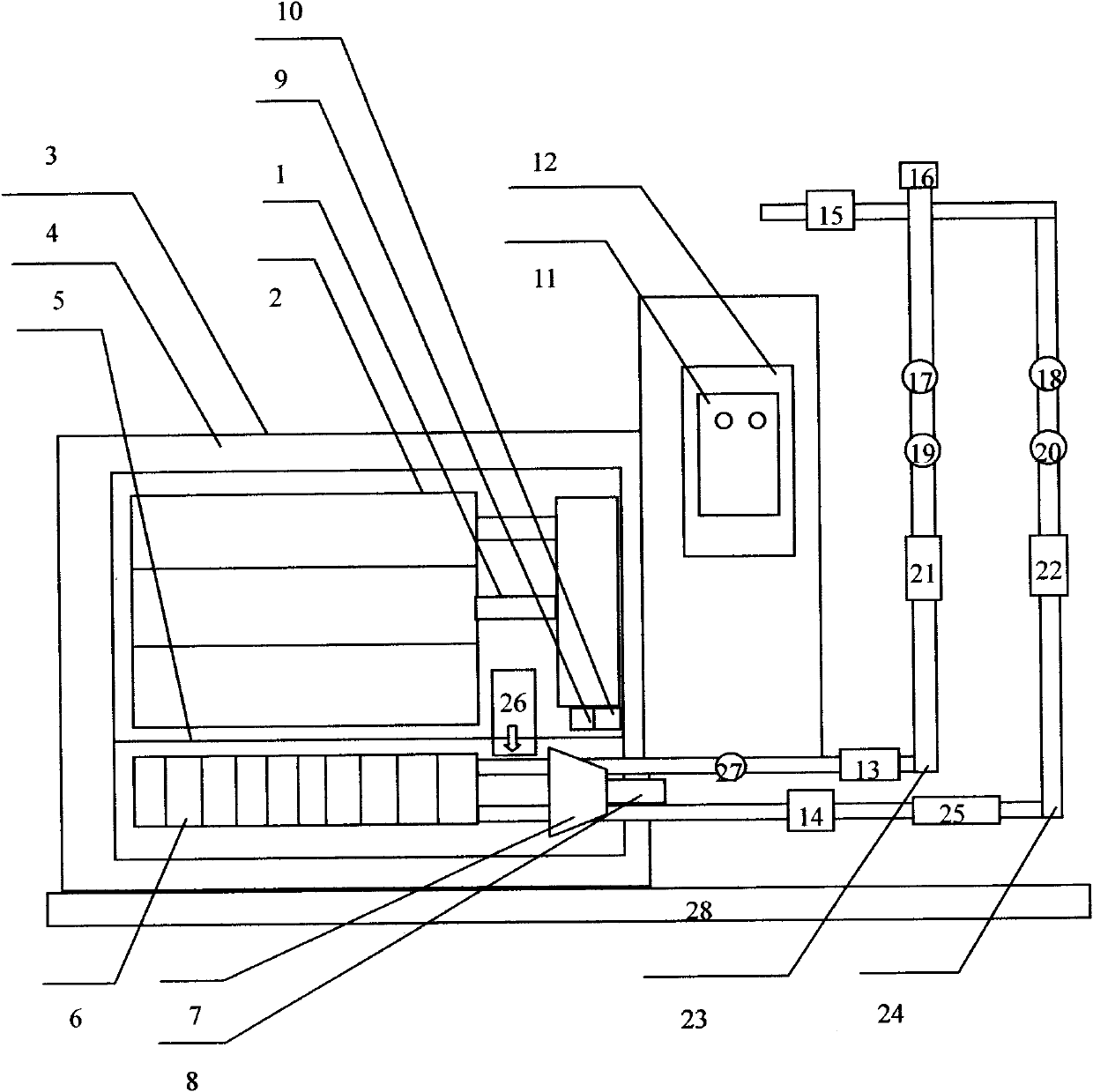
[0045] A certain factory is equipped with a regenerative heat supply unit provided by the present invention, which uses the heat accumulator provided by the present invention. The shell of the heat accumulator is a high-temperature heat insulating material 4, and the heat storage brick 2, the heat exchange pipe 6, the fan 7, and the electric heater 1 are arranged in the shell.

[0046] The heat storage brick 2 is an iron heat storage brick, preferably the main component is more than 85% of ferric oxide and some minerals; The calcium content is less than 1%, and there are a large number of spiral pores in the microscopic view. The heat storage brick 2 is a cuboid, and several, dozens to hundreds of blocks can be used in one heat accumulator.

[0047] The heat exchange pipe 6 is made of heat-resistant metal or alloy, which can be a nickel alloy pipe, stainless steel pipe, etc. In order to improve the heat exchange efficiency, it can be arranged in a coiled manner. In order to i...

Embodiment 2

[0064] The structure of this regenerative heat supply unit is the same as that of Embodiment 1, except that the regenerative bricks use magnesium oxide as the main raw material, and the heat storage temperature can also reach 100-800 degrees Celsius.

Embodiment 3

[0066] The structure of this regenerative heat supply unit is the same as that of Embodiment 1, except that the regenerative bricks use aluminum or silicate as the main raw material, and the heat storage temperature can also reach 100-800 degrees Celsius.


PUM


Abstract

The invention aims to overcome the defects of the existing heating equipment such as boilers and the like, and provides a heat-accumulating heat supply unit, which uses heat-accumulating bricks as a heat-accumulating medium, has a heat-release-process-controllable large-capacity heat-accumulating structure, and is a heat-release-process-controllable large-capacity heat-accumulating heat supply unit. In particular, the invention provides a heat accumulator for storing heat for the heat-accumulating heat supply unit, and a shell of the heat accumulator is made of high-temperature insulating material; and heat-accumulating bricks, a heat exchange water pipe, a fan and an electric heater are arranged in the shell. The heat-accumulating heat supply unit comprises a thermal insulation system, a conduction system, a control system and a safety system except the heat accumulator.

Description

technical field [0001] The invention relates to a heat storage heat supply unit, in particular to a heat storage heat supply unit with a unique heat storage structure. Background technique [0002] Currently feasible heating systems and heat sources for domestic hot water supply systems mainly include coal-fired boilers, oil-fired boilers, gas-fired boilers, solar boilers and electric heaters. Generally, the operating cost of coal-fired boilers is low, but the exhaust gas, waste, waste water, etc. discharged will cause serious pollution to the environment; the exhaust gas of oil-fired boilers and gas-fired boilers has less environmental pollution, but the operating costs are high; solar energy is the cleanest Energy, but at present, the conversion efficiency of photoelectric and photothermal energy is low, the output is not stable enough, and the application cost of providing large heat capacity is too high; although general electric boilers have no emissions and no pollutio...

Claims


Application Information

Patent Timeline
Patent Type & Authority Applications(China)
IPC IPC(8): F28D20/00F24D11/00F24D13/00F24H7/04
CPCY02E60/142Y02E60/14
Inventor 李岩高君马强
Owner 北京蓝景圣诺尔新能源技术有限公司
Why Eureka
Try Eureka