LED light source using filter with dual-function of stopping ultraviolet rays and infrared rays

A technology of LED light source and optical filter, which is applied in the field of optical filtration, can solve the problems of no filtering, etc., and achieve the effects of simple preparation method, reduction of light radiation hazards, and high ultraviolet cut-off rate

CN101813296BInactive Publication Date: 2012-06-27李欣洋
0 Cites 0 Cited by

Patent Information

Authority / Receiving Office
CN · China
Patent Type
Patents(China)
Current Assignee / Owner
Publication Date
2012-06-27
Estimated Expiration
Not applicable · inactive patent

Smart Images

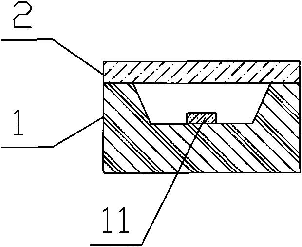
  • Figure 1
    Figure 1
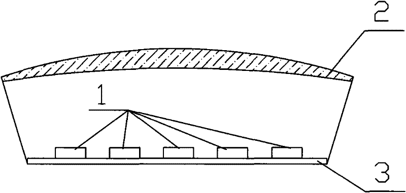
  • Figure 2
    Figure 2
  • Figure 3
    Figure 3
Patent Text Reader

Abstract

The invention provides an LED light source using a filter with dual functions of stopping ultraviolet rays and infrared rays. The LED light source comprises an LED device and the filter, wherein the LED device is provided with at least one LED chip; and the filter is arranged on the LED device and is used for filtering light rays emitted from the LED chip; the light emitted from the LED chip emitto the external through the filter; the filter can be added when the LED device is encapsulated or can be arranged when the LED device is secondarily encapsulated; or a plurality of LED devices use the same filter. The filter is a transparent substrate which has the dual functions of stopping the ultraviolet rays and the infrared rays and is molded by any one of materials of ARTON, COC, COP, PMMAand optical glass; an ultraviolet stopping film and an infrared stopping film are plated on the surface of the filter; and the filter can absorb the light in a short wavelength range in which the wavelength is less than 445 nm and a long wavelength range in which the wavelength is greater than 700 nm. The invention also provides the filter with the dual functions of stopping the ultraviolet rays and the infrared rays and a preparation method thereof.
Need to check novelty before this filing date? Find Prior Art

Description

technical field

[0001] The invention belongs to the technical field of LED lighting. Specifically related to light filtering technology. technical background

[0002] With the advent of ultra-bright LEDs, their efficiency is getting higher and higher, and their prices are gradually falling. At the same time, LED has the characteristics of long life, shock resistance, high luminous efficiency, no interference, no fear of low temperature, no mercury pollution and high cost performance. It is a great potential product that is favored by the semiconductor industry to replace traditional lighting appliances. Ultra-high-brightness LEDs have greatly expanded the application of LEDs in various signal display and lighting source fields, such as interior and exterior lights of automobiles, various traffic lights, indoor and outdoor information displays and backlights. Using LED products for lighting will provide a wider application space for LEDs.

[0003] As the application range ...

Examples

Embodiment 1

[0051] see figure 1 , an LED device 1, in which an LED chip 11 is packaged, and an optical filter 2 is located above the LED chip 11 and fixed.

[0052] When working, the light emitted by the LED chip 11 must pass through the optical filter 2 before it can be emitted to the outside. The optical filter 2 filters the light emitted by the LED chip within the range of wavelengths less than 445nm and greater than 700nm.

[0053] LED chip 11 can choose any desired emission wavelength, such as green light with a dominant wavelength of 530nm, or red light with a dominant wavelength of 620nm; another example is blue light with a dominant wavelength of 460nm, and mix a certain proportion in the potting glue YAG powder, the blue light emitted by the LED chip excites the YAG powder, and finally obtains white light with a color temperature of 8000K or other required color temperatures.

[0054] The preparation of the optical filter with dual functions of cutting off ultraviolet rays and i...

Embodiment 2

[0066] It is basically the same as Example 1, the difference is the preparation of the optical filter. Firstly, the inner layer film is deposited by electron beam evaporation on the transparent substrate with the silicon target and the tantalum pentoxide target. On this basis, the titanium oxide -The cerium oxide target is subjected to electron beam evaporation to coat the outer film to obtain the product.

Embodiment 3

[0068] Basically the same as Embodiment 1, the difference is that the optical filter is formed into a circular lens surface by a transparent substrate, such as figure 2 shown; or shaped into a square lens surface, and then cleaned and coated.